Optical amplifier and method of manufacturing optical amplifier

a technology of optical amplifier and optical fiber, applied in the field of optical amplifier, can solve the problems of increasing cost, difficult in reality to implement the optical fiber-based optical amplifier with a smaller size, weakening the optical power of the optical signal, etc., and achieves the effects of reducing system cost, increasing price competitiveness, and maximizing space usag

Active Publication Date: 2017-07-18
LICOMM
View PDF5 Cites 8 Cited by
  • Summary
  • Abstract
  • Description
  • Claims
  • Application Information

AI Technical Summary

Benefits of technology

[0033]As described above, the apparatus or method according to an exemplary of the present invention allows to maximize a space usage with an optical transceiver standardized with no separate slot room to accommodate an optical amplifier therein.
[0034]This may cause a decrease...

Problems solved by technology

However, the longer the optical signals travels, the weaker the optical power of the optical signal.
Thus, auxiliary components or structures such as a guide, a holder, etc....

Method used


Image

  • Optical amplifier and method of manufacturing optical amplifier
  • Optical amplifier and method of manufacturing optical amplifier
  • Optical amplifier and method of manufacturing optical amplifier

Examples


Embodiment Construction

[0046]Hereinafter, preferred exemplary embodiments of the present invention will be described with reference to accompanying drawings in order to describe the present invention in detail to the extent that a person skilled in the art to which the invention pertains can easily enforce the technical concept of the present invention. It will be understood that various modifications in form and details may be made thereto without departing from the spirit and scope of the present invention.

[0047]In the drawings, the shapes, dimensions, etc., of elements may be exaggerated for clarity, and the same reference numerals may designate the same or like elements throughout the specification and drawings.

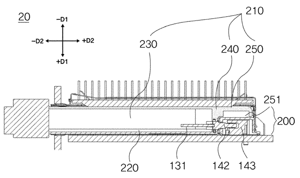
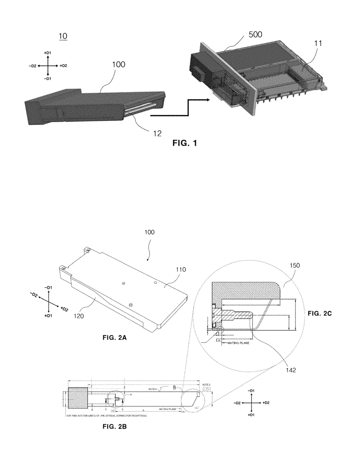
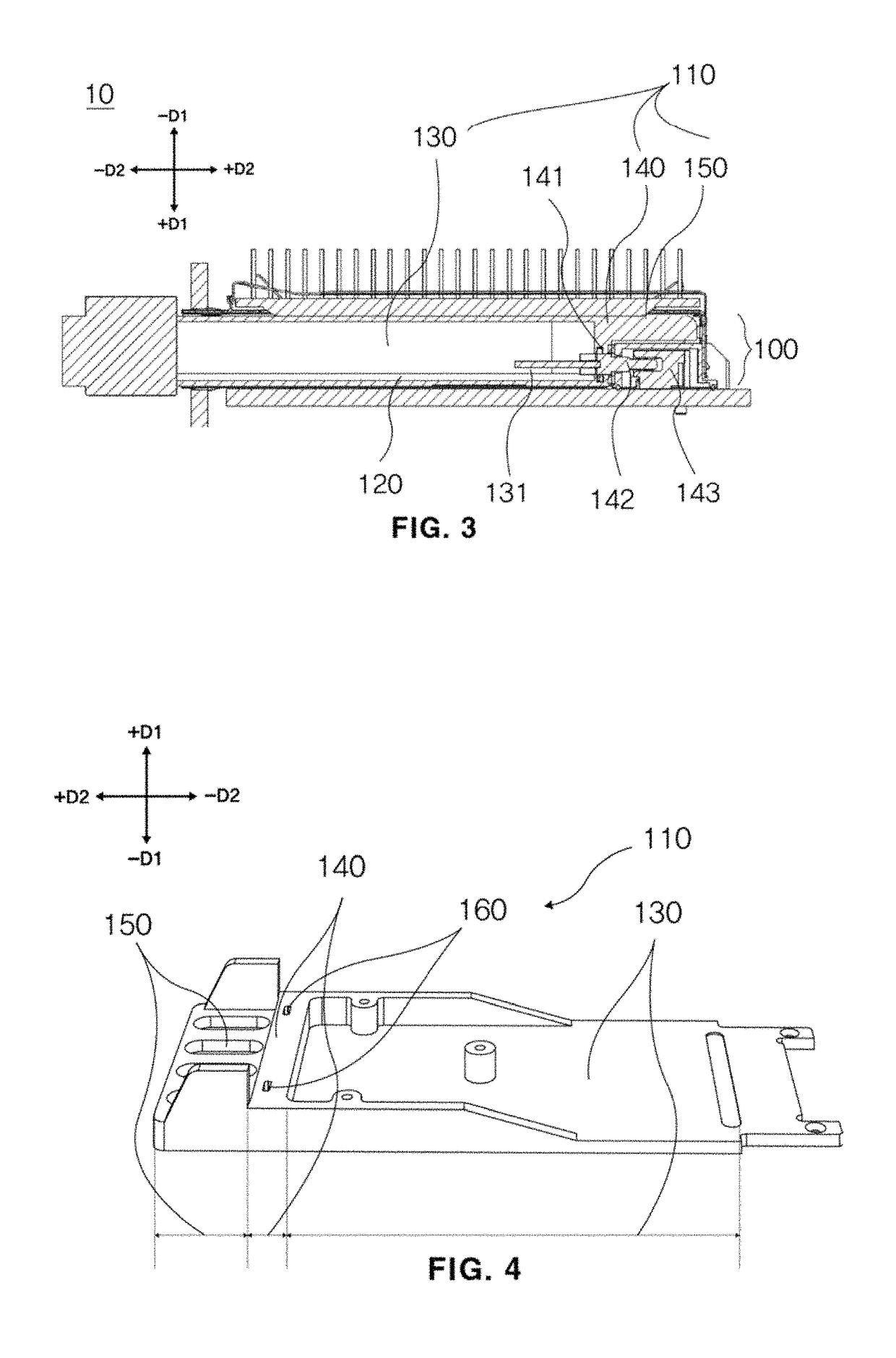
[0048]FIG. 2A depicts a top-view diagram of the case 100 whose top and bottom portions 110 and 120 are coupled to each other. Here, the top portion 110 of the case 100 is one positioned toward the direction −D1 (e.g., a downward direction of FIG. 1), and the bottom portion 120 of the case 100 i...


PUM


Abstract

An apparatus comprising a case, an optical amplifier, and an optical transceiver is provided. The optical amplifier and the optical transceiver are included in the case. The case includes a top portion and a bottom portion. The top portion includes first to third sections arranged in a direction perpendicular to a direction extending from the top portion to the bottom portion. The first section has a larger area than the third section and the second section divides the first and third sections. The third section includes a first cavity including at least one portion of the optical amplifier. The optical amplifier is provided using at least one of an amplifying fiber, a pumping light source, an isolator, a wavelength-division multiplexer (WDM) coupler, a wavelength-variable optical filter, a monitoring-tap photo diode, and a driving control unit.

Description

CROSS-REFERENCE TO RELATED APPLICATION[0001]This application claims priority under 35 U.S.C. §119 from Korean Patent Application No. 10-2016-0099351, filed on Aug. 4, 2016, in the Korean Intellectual Property Office (KIPO), the disclosure of which is incorporated by reference herein in its entirety.TECHNICAL FIELD[0002]The present Invention relates to an optical amplifier, and more particularly to, an optical amplifier that can be mounted in a standardized optical transceiver case.DISCUSSION OF THE RELATED ART[0003]Due to spread and increase of the Internet and data service, demands for broadband communication networks have been increased and thus, a bandwidth required in an optical communication technology has been increasing. Thus, a technology Innovation for realizing an ultra-broadband era beyond the broadband era has been strongly demanded.[0004]Data rates of broadband transmission networks for transferring the broadband signals have been developed, e.g., from 2.5 Gbps to 10 Gb...

Claims


Application Information

Patent Timeline
IPC IPC(8): H01S3/067H01S3/094H01S3/00G02B6/42
CPCH01S3/06704H01S3/06754H01S3/0064G02B6/4246G02B6/4262G02B6/4286G02B6/4215H01S3/094003
Inventor KIM, SUNG JUNKIM, JEONG MEEYOON, SOO YOUNGLEE, JUNG KWON
Owner LICOMM
Why Eureka
Try Eureka