Driver and image instrument

a technology of image instruments and drivers, applied in the direction of piezoelectric/electrostrictive device details, printers, camera focusing arrangement, etc., can solve the problems of motor oscillation and becoming uncontrollable, inability to drive with a predetermined drive amount or less for this minute driving, and complicated configuration and increase in siz

Active Publication Date: 2017-07-18
OM DIGITAL SOLUTIONS CORP
View PDF29 Cites 1 Cited by
  • Summary
  • Abstract
  • Description
  • Claims
  • Application Information

AI Technical Summary

Benefits of technology

[0007]The movable frame which holds the photographic lens needs to be driven rapidly and precisely (with high positional precision) to accurately utilize a photographing opportunity. An electromagnetic motor such as a stepping motor or a voice coil motor is generally used to rapidly drive the movable frame.

Problems solved by technology

Thus, in an image instrument such as a camera, the configuration is complicated and increased in size.
However, the problem of these motors is that the motors oscillate and become uncontrollable in rapid driving at a predetermined velocity or more.
Another problem of these motors is that if minute driving is attempted to drive the motors precisely (with high positional precision), driving with a predetermined drive amount or less for this minute driving is impossible.

Method used


Image

  • Driver and image instrument
  • Driver and image instrument
  • Driver and image instrument

Examples


first embodiment

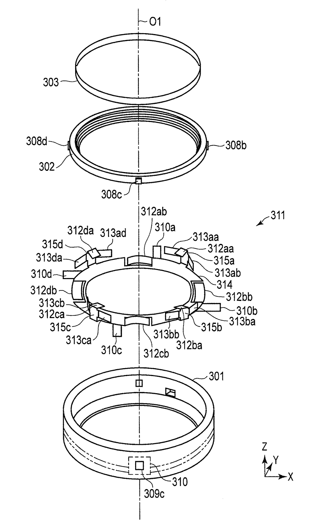
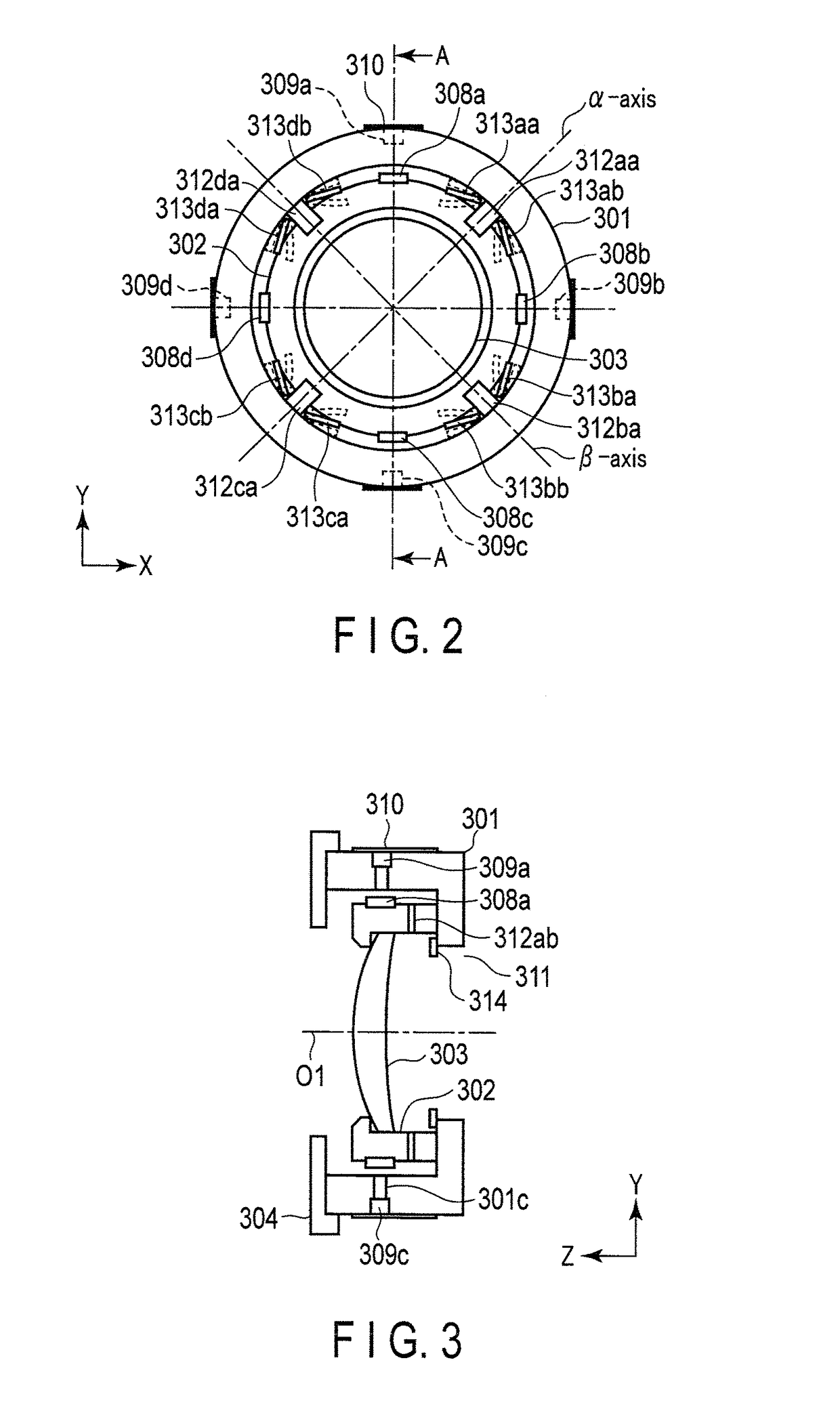
[0042]Hereinafter, a first embodiment of the present invention will be described with reference to the drawings. In each of the drawings used in the following explanation, each component has a different scale so that the size of each component can be recognized on the drawings. The present invention is not limited solely to the number of components, the shapes of the components, the ratio of the sizes of the components, and the positional relation between the components shown in the drawings below.

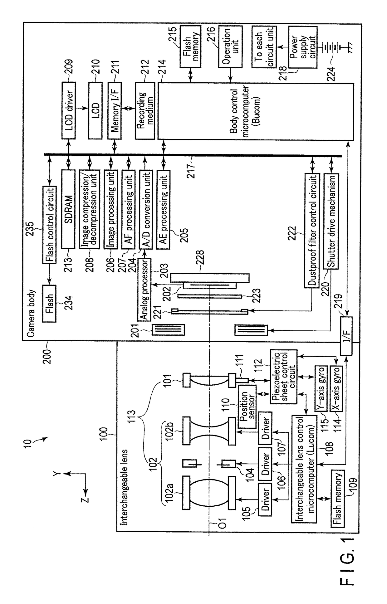
[0043]FIG. 1 shows a block diagram of a configuration example of a camera system (digital camera) 10 to which an operational device according to the present embodiment of the present invention is applied. In this camera system 10, a direction from a camera body 200 toward a subject is referred to as the front, and the opposite direction is referred to as the rear. An axis corresponding to an optical axis O1 of an optical system constituted by an interchangeable lens 100 is a Z-axis, and tw...

second embodiment

[0244]Now, a second embodiment of the present invention is described with reference to FIG. 20 to FIG. 22. The same parts as those in the first embodiment described above are provided with the same signs and are not described in detail.

[0245]FIG. 20 shows a front view of a driver corresponding to FIG. 2 in the first embodiment described above. FIG. 21 shows a development diagram of a piezoelectric sheet used in the present embodiment, and corresponds to FIG. 5 in the first embodiment described above. FIG. 22 shows a sectional side view taken along the line F-F in FIG. 20.

[0246]A first difference is described.

[0247]While the movable frame 302 which holds the lens 303 is driven by the piezoelectric sheet 311 in the first embodiment described above, a lens 603 is directly driven by a piezoelectric sheet 611 in the present second embodiment.

[0248]Such a configuration permits the driver to be reduced in size by the thickness and the flexibility of the piezoelectric sheet 611. The lens 60...


PUM


Abstract

A driver includes a piezoelectric sheet, a fixing frame, a moving frame, and a control circuit. The piezoelectric sheet includes a first piezoelectric body portion which bends in a first direction, a second piezoelectric body portion which bends in a second direction that intersects at right angles with the first direction, and a connection portion which connects the first and second piezoelectric body portions. The fixing frame is fixed to the connection portion. The moving frame is supported on the first and second piezoelectric body portions. The control circuit applies voltage signals to the first and second piezoelectric body portions to bend the first and second piezoelectric body portions and which moves the moving frame in one of the first direction and the second direction or in a composite direction of the first direction and the second direction.

Description

CROSS-REFERENCE TO RELATED APPLICATIONS[0001]This application is a Continuation application of PCT Application No. PCT / JP2015 / 059159, filed Mar. 25, 2015 and based upon and claiming the benefit of priority from the prior Japanese Patent Application No. 2014-079660, filed Apr. 8, 2014, the entire contents of both of which are incorporated herein by reference.BACKGROUND OF THE INVENTION[0002]1. Field of the Invention[0003]The present invention relates to a driver and an image instrument which uses the driver, the driver driving a movable frame which is included a photographic lens and is driven for an image blur correction and focusing during imaging or which is included a camera and is a movable frame (moving frame, lens) holding a lens constituting the photographic lens.[0004]2. Description of the Related Art[0005]Recently, digital cameras which enable not only still image photography but also moving image photography have been on the market. When autofocus is performed in the photo...

Claims


Application Information

Patent Timeline
Patent Type & Authority Patents(United States)
IPC IPC(8): H04N5/232G02B7/04G02B7/02H01L41/09G02B7/09H01L41/053H01L41/083G02B27/64H01L41/04
CPCH04N5/23287G02B7/02G02B7/04G02B7/09G02B27/646H01L41/042H01L41/053H01L41/083H01L41/0926G03B2205/0061G03B3/10G03B5/00H02N2/028G03B2205/0007H10N30/874H10N30/503H10N30/2042H10N30/857H04N23/687H10N30/50H10N30/88H10N30/204H10N30/802
Inventor KAWAI, SUMIO
Owner OM DIGITAL SOLUTIONS CORP
Why Eureka
Try Eureka