Radio positioning of a mobile receiver using a virtual positioning reference

a mobile receiver and virtual positioning technology, applied in vehicle position/course/altitude control, process and machine control, instruments, etc., can solve the problems of inability to calculate transmitter clock offset a and local clock error c values, and the inability to synchronize the available terrestrial radio signal transmitters. to achieve the effect of reducing physical circuitry, improving localization, and reducing the complexity of the guidance system

Active Publication Date: 2017-07-25
BAE SYSTEMS PLC
View PDF20 Cites 1 Cited by
  • Summary
  • Abstract
  • Description
  • Claims
  • Application Information

AI Technical Summary

Benefits of technology

[0031]The apparatus and method of this first aspect of the present invention thereby exploits the clock stability of the transmitter from which a virtual positioning reference is established by assuming that the clock offset associated with the transmitter will not change during the time in which the autonomous vehicle is moving between the first and second positions. Assuming a stable transmitter clock, it is thereby possible to relieve the autonomous vehicle from the computational burden of needing to calculate the transmitter clock offset, because the offset is eliminated during the step of determining the time difference between when the virtual positioning reference is predicted to receive the second instance of the code word and when the autonomous vehicle actually receives the second instance of the code word. In other words, because a differential method is used for determining the position of the autonomous vehicle, it is not necessary to calculate the transmitter clock offset. This approach will only be valid if the transmitter clocks exhibit high levels of stability, so that there no significant error accrues between the time that the most recent virtual positioning reference is established and the time that the autonomous vehicle determines its position at an unknown location. Fortunately, modern digital opportunistic signal sources such as cellular, DAB, DVB, etc transmissions exhibit very high stabilities that allow the present method to be utilized for many hours after establishing a virtual reference.
[0056]In embodiments, the autonomous vehicle is able to receive transmissions from a plurality of transmitters. This allows a “single difference” calculation to be performed so as to remove any effect of a local clock error. Thus it is not necessarily required to undertake the computationally burdensome task of establishing a local clock error model. The single different calculation can be performed by taking the differences between pairs of measurements from different transmitters. This leaves the effects of multipath interference, signal geometry and measurement noise as the main sources of error.

Problems solved by technology

However, opportunistic terrestrial radio signal transmitters that are available to a positioning system are not usually synchronized—even if they are set up to transmit the same radio signal type, with the same code word repeat rate.
As can be observed from a navigation system such a GPS, synchronization between the radio signal sources is very useful for radio localization—but is often not possible in an environment in which opportunistic, unsynchronized terrestrial radio signals are the only radio signal sources available for localization.
However, the calculation of the transmitter clock offset a and local clock error c values can be computationally expensive, especially when considering that multiple transmitters are required for effective self-localization.
Furthermore, if a vehicle employs a relatively cheap and simple navigation device, the local onboard clock is not likely to be stable.
Therefore, the calculated value of a local clock error at one instance may not necessarily apply at another instance, thereby adversely affecting the position calculation.
While it is possible to obtain a highly stable clock reference using an atomic clock, or via a GPS fix, these are not necessarily practical solutions for many vehicles.
Atomic clock references are heavy, expensive and unsuitable for use in many vehicle navigation devices.
A stable timing reference can be obtained via GPS, but this relies on availability of a continuous GPS fix, and so is not possible under conditions in which a GPS signal cannot be obtained.
To do this is computationally expensive, and so undesirable in many vehicles, such as a small, remotely controlled or autonomous vehicle in which content weight, processing power, and battery life are valuable resources.
These are problems associated with the prior art devices that make use of the above Equation 1.

Method used


Image

  • Radio positioning of a mobile receiver using a virtual positioning reference
  • Radio positioning of a mobile receiver using a virtual positioning reference
  • Radio positioning of a mobile receiver using a virtual positioning reference

Examples


Embodiment Construction

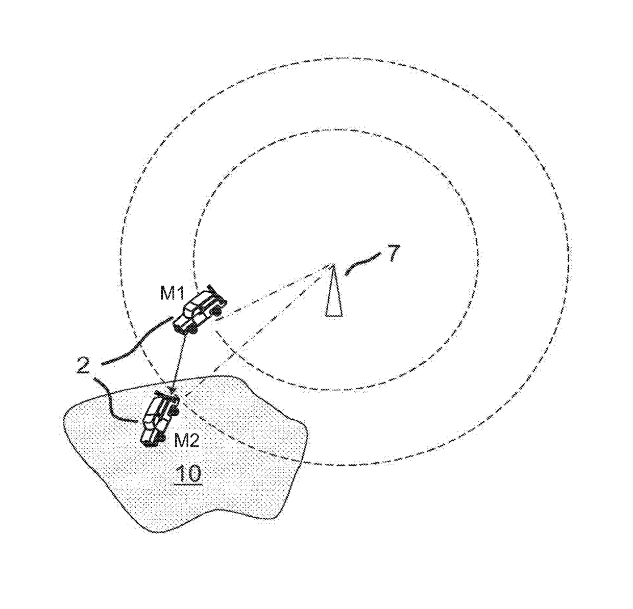
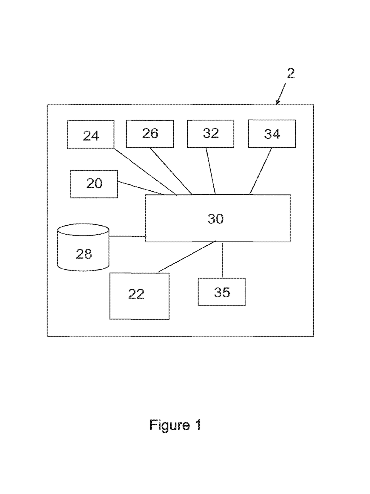
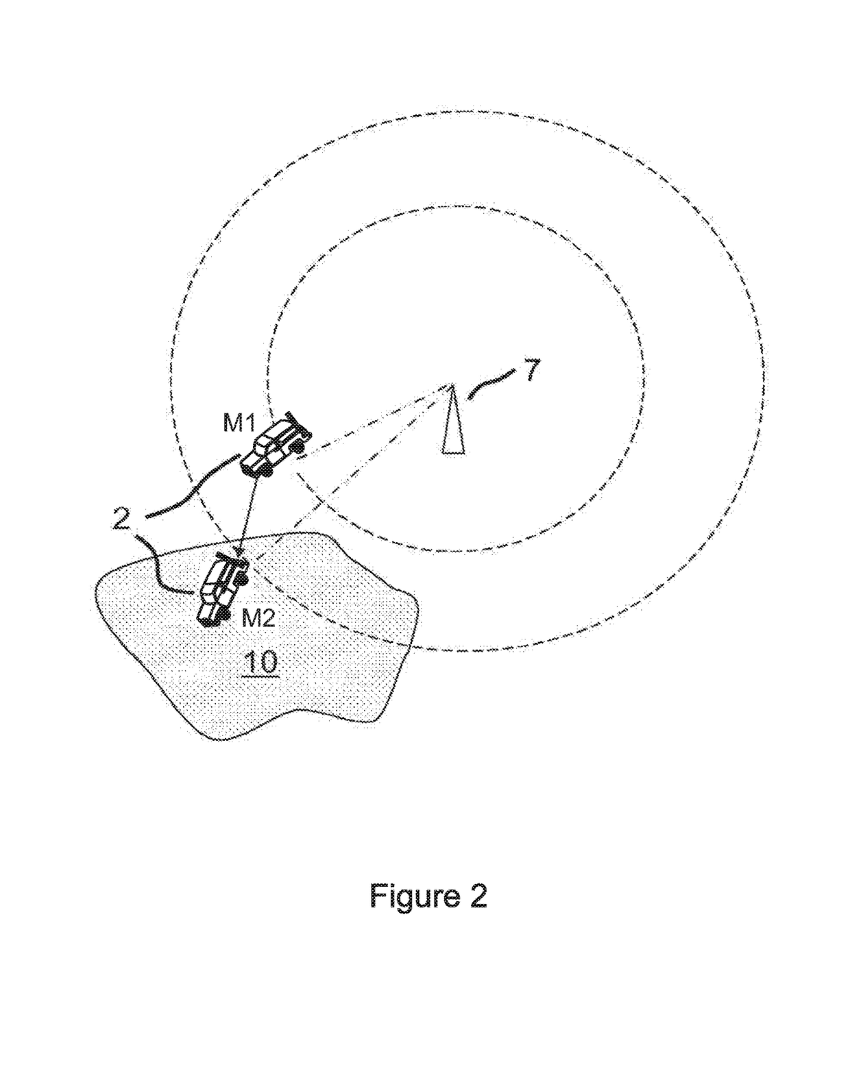
[0103]Referring to FIG. 1 there is schematically shown a guidance system for an autonomous vehicle 2 according to a first embodiment of the present invention. The guidance system includes a primary positioning resource in the form of a GPS receiver 20, a terrestrial radio signal receiver 22, an Inertial Measurement Unit (IMU) 24, an interface module 26, a database 28, a general purpose processor 30, a user interface module 32, a vehicle control module 34 and a secondary processor 35 in the form of a differential positioning module dedicated to performing differential timing and distance calculations. The autonomous vehicle 2 is also equipped with a clock incorporated as part of the processor 30.

[0104]The GPS receiver 20 and terrestrial receiver 22 collect data from respective GPS and terrestrial radio signals as is known in the art, and send their data to the processor 30. The processor 30 also receives data from the IMU 24, and optionally, the interface module 26. The interface mod...


PUM


Abstract

Methods and systems are disclosed for radio positioning of a vehicle using a virtual positioning reference established by logging a known position of the vehicle together with a local time that a first instance of a predictably repeated code word is received from an opportunistic terrestrial radio transmitter. During movement of the vehicle to a second, unknown position, a local clock is used to determine the time difference between when the virtual positioning reference is predicted to receive a second instance of the code word and when the vehicle actually receives the second instance of the code word, thereby providing positioning information when traditional navigation signals such as GPS are not available. The radio positioning information is then used to initiate an action such as recording the location information for future retrieval by a user, and / or controlling the movements of an autonomous vehicle.

Description

RELATED APPLICATIONS[0001]This application is a continuation in part of U.S. application Ser. No. 13 / 500,016, which is herein incorporated by reference in its entirety for all purposes. U.S. application Ser. No. 13 / 500,016 is a national phase application filed under 35 USC §371 of PCT Application No. PCT / GB2010 / 051654 with an International filing date of Oct. 4, 2010. PCT Application No. PCT / GB2010 / 051654 claims priority of the following: GB Patent Application 0917388.1 filed Oct. 5, 2009, EP Patent Application 09275092.6 filed Oct. 5, 2009, GB Patent Application 0917384.0 filed Oct. 5, 2009, EP Patent Application 09275091.8 filed Oct. 5, 2009, GB Patent Application 0920772.1 filed Nov. 27, 2009, EP Patent Application 09177349.9 filed Nov. 27, 2009, GB Patent Application 1009486.0 filed Jun. 7, 2010, EP Patent Application 10275059.3 filed Jun. 7, 2010, and GB Patent Application 1013413.8 filed Aug. 10, 2010. Each of these applications is herein incorporated by reference in their ent...

Claims


Application Information

Patent Timeline
Patent Type & Authority Patents(United States)
IPC IPC(8): G01S5/02G01S19/07G05D1/02G01S19/48G01C21/20
CPCG01S5/0263G01C21/20G01S5/021G01S19/07G01S19/48G05D1/0278G05D1/0285G05D2201/0213
Inventor FARAGHER, RAMSEY MICHAEL
Owner BAE SYSTEMS PLC
Why Eureka
Try Eureka