
Computing device, method, and computer program for controlling cooling fluid flow into a computer housing

a computer and cooling fluid technology, applied in the field of computing devices and computer programs, can solve the problems of under-cooling or over-cooling of computing devices, and the cooling fluid does not necessarily get, and achieve the effect of good supply

Inactive Publication Date: 2017-08-01
FUJITSU LTD
View PDF17 Cites 0 Cited by
  • Summary
  • Abstract
  • Description
  • Claims
  • Application Information

AI Technical Summary

Benefits of technology

This approach enables efficient cooling distribution without a centralized control system, reducing energy consumption and administrative burdens, while ensuring adequate cooling for all devices, even in dynamic environments.

Problems solved by technology

Under-cooling or over-cooling of computing devices can occur when computing devices are configured to behave greedily with regard to cooling resources.
Cooling fluid does not necessarily get to where it is needed, and may disproportionately be drawn to locations where only a small amount is required.

Method used


Image

  • Computing device, method, and computer program for controlling cooling fluid flow into a computer housing
  • Computing device, method, and computer program for controlling cooling fluid flow into a computer housing
  • Computing device, method, and computer program for controlling cooling fluid flow into a computer housing

Examples


Embodiment Construction

[0066]FIG. 4 is a schematic illustration of a computing device 10 embodying the present invention. Certain typical components of a computing device 10 are omitted for illustration purposes, but computing devices 10 embodying the present invention may also comprise one or more of the following components: cpu, a storage unit, memory, I / O devices, motherboard, display unit. Furthermore, one or more of those components may provide hardware contributing to the functionality of the illustrated components. The illustrated components are a temperature monitor 12, a cooling fluid drawing mechanism 14, a cooling fluid drawing controller 16, and an indication receiver 20. The indication receiver 20 is illustrated in dashed lines to denote that it is optional in invention embodiments, although some means for generating and / or receiving indications is required, it may, for example, be a function of another component, such as the cooling fluid drawing controller 16. The components are housed wit...


PUM


Abstract

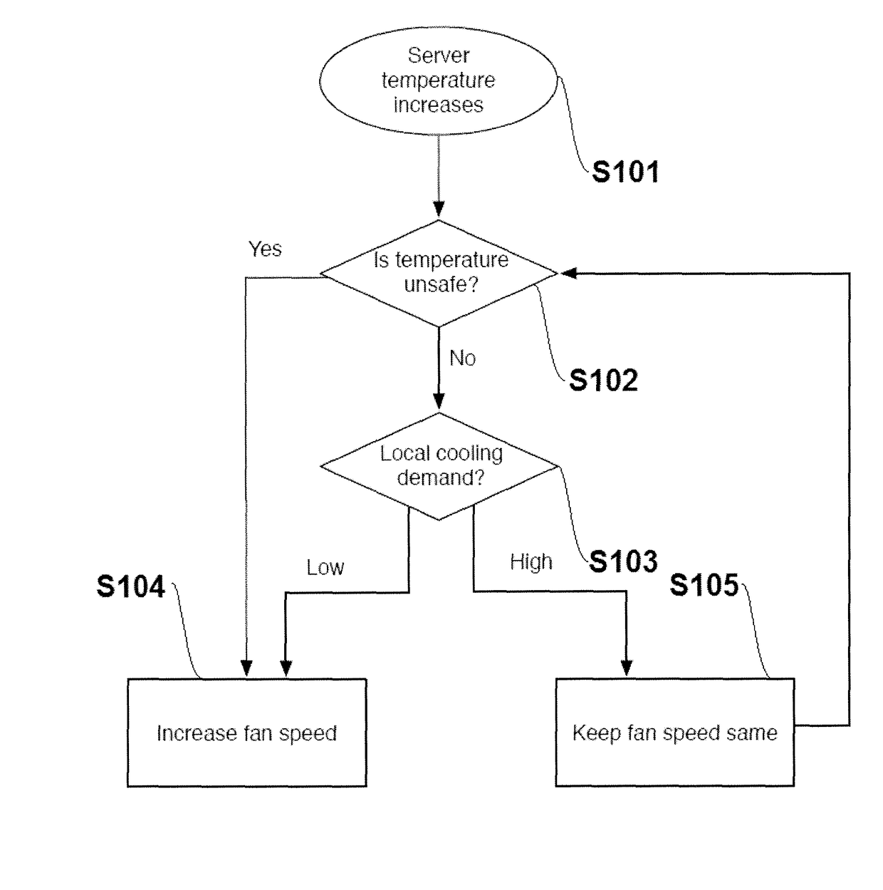
A computing device having a housing; a temperature monitor to monitor a temperature within the housing; a cooling fluid drawing mechanism to draw cooling fluid into the housing; a cooling fluid drawing controller, when the computing device is installed within an enclosure as one of plural computing devices, to obtain a value representing the temperature, and if the value is within a predetermined range, to select an operating state for the mechanism from among a first state in which the mechanism draws fluid into the housing at a first rate, and a second state in which the mechanism draws cooling fluid into the housing at a second rate lower than the first rate, and to run the mechanism in the selected state; where the selection of the state is based on demand for cooling from other computing devices from among the plurality of computing devices.

Description

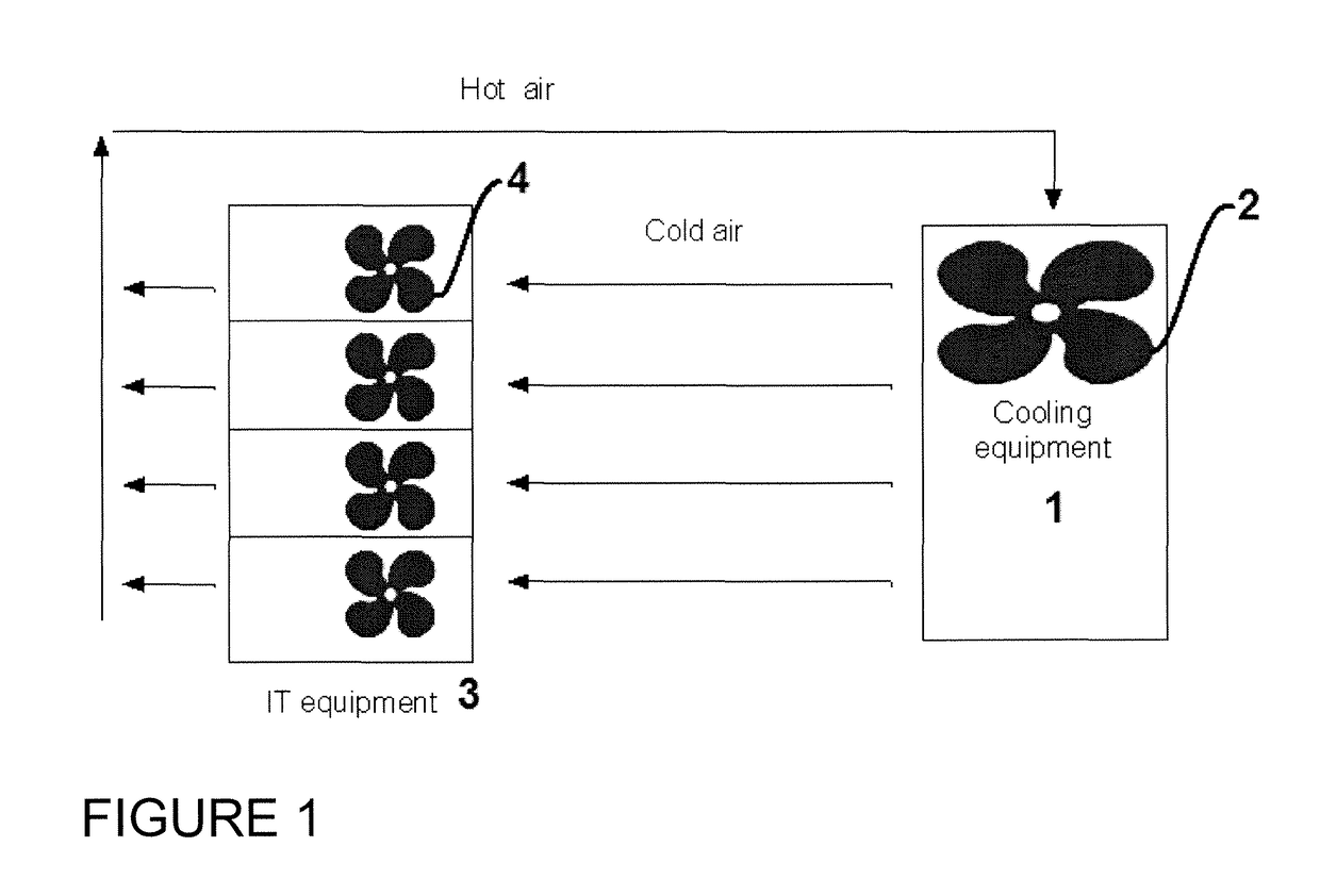
CROSS REFERENCE TO RELATED APPLICATIONS[0001]This claims the benefit of European Application No. 13187272.3, filed Oct. 3, 2013, the disclosure of which is incorporated herein by reference.BACKGROUND OF THE INVENTION[0002]The present invention relates to a method, computing device and computer program for controlling the rate at which cooling fluid is drawn into a computer housing. In particular, embodiments have application in computing devices housed in enclosures such as data centre halls.[0003]The equipment in data centres, such as computer servers and storage devices, generates a lot of heat while it operates. In most data centres this heat is removed by moving air through the data centre, see FIG. 1, which provides an overview of airflow in a data centre. Cool air is introduced into the data centre hall by cooling equipment 1 and it is forced to flow towards the IT equipment by a set of fans 2 external to the IT equipment. The cool air is then introduced into one end of the IT...

Claims


Application Information

Patent Timeline
Patent Type & Authority Patents(United States)
IPC IPC(8): H05K7/20G06F1/20
CPCH05K7/20836G06F1/20H05K7/20736H05K7/20745G06F1/206Y02D10/00
Inventor BERGHE, SVEN VAN DEN
Owner FUJITSU LTD
Learn More