
Life degradation mitigation for transient response energy storage

a technology of transient response and energy storage, which is applied in the direction of dc source parallel operation, emergency power supply arrangement, transportation and packaging, etc., can solve the problems of insufficient power output of the genset at such low speeds to maintain the desirable operation of each connected load, not providing optimal fuel efficiency, and selective limitation of current supplied to electric loads

Active Publication Date: 2017-08-08
CATERPILLAR INC
View PDF13 Cites 1 Cited by
  • Summary
  • Abstract
  • Description
  • Claims
  • Application Information

AI Technical Summary

Benefits of technology

Optimizes genset operation by efficiently meeting load demands during transients, enhancing fuel efficiency and extending energy storage device lifespan through predictive maintenance and controlled speed adjustments based on SOH and temperature.

Problems solved by technology

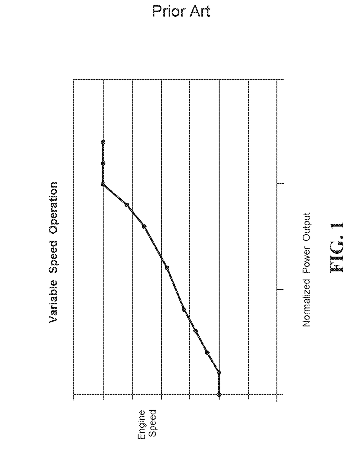
During transient or step load conditions when the primary power source (for example, an engine) speeds are relatively low, the power output by the genset at such low speeds may be insufficient to maintain desirable operation of each connected load.
Such an arrangement may not provide optimal fuel efficiency.
Current supplied to electric loads is selectively limited when the estimated electric power supple voltage is smaller than a predetermined value.
Although the '117 Application may describe a methodology for limiting current to loads, the '117 Application does not disclose a system or method for utilizing battery health for optimizing the speed of a power source to meet load demands.

Method used


Image

  • Life degradation mitigation for transient response energy storage
  • Life degradation mitigation for transient response energy storage
  • Life degradation mitigation for transient response energy storage

Examples


Embodiment Construction

[0014]Reference will now be made in detail to specific embodiments or features, examples of which are illustrated in the accompanying drawings. Generally, corresponding reference numbers will be used throughout the drawings to refer to the same or corresponding parts, unless otherwise specified.

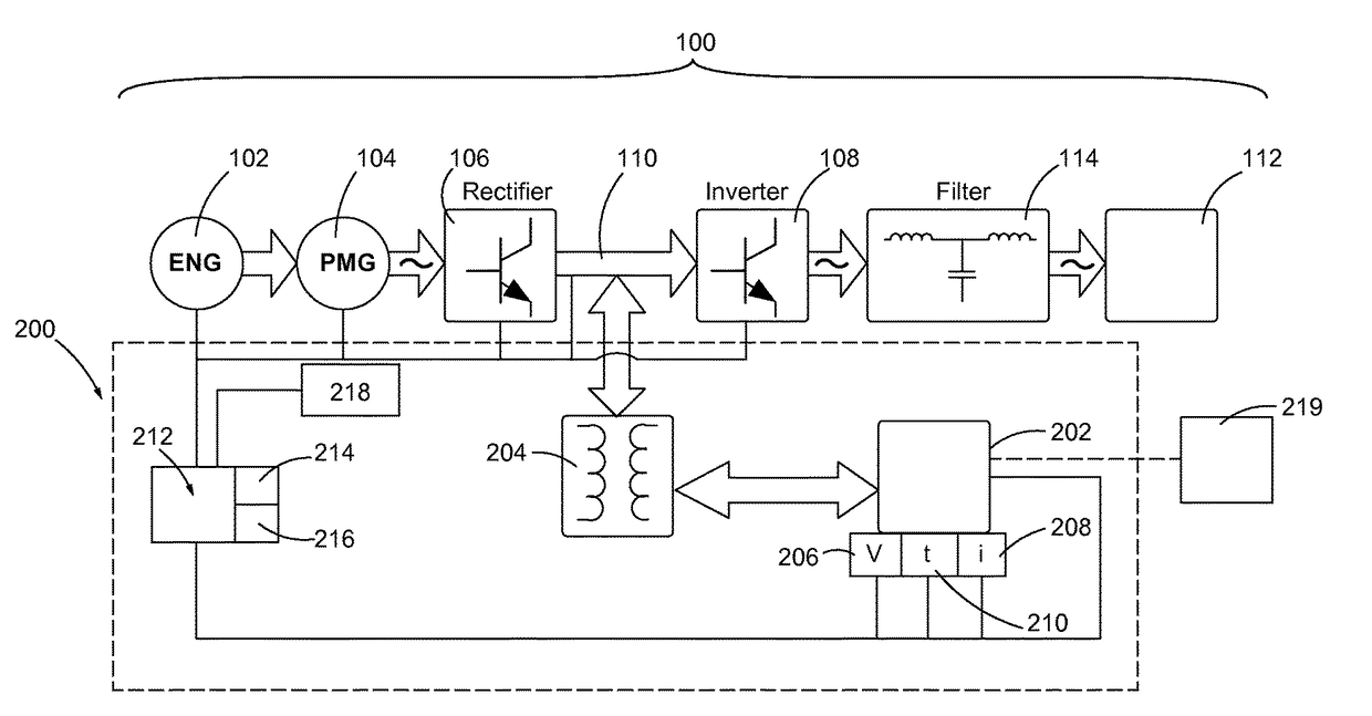
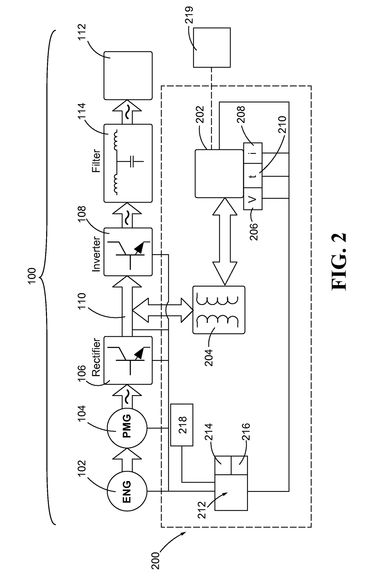
[0015]FIG. 2 diagrammatically illustrates one exemplary variable speed genset system 100 that may be employed in stationary power generation applications or in conjunction with industrial work machines, stationary drive machines, mobile work vehicles, hybrid electric vehicles, machine tools, and the like. As shown, the variable speed genset system 100 may generally include a primary power source 102, an electric machine 104, a rectifier circuit 106, an inverter circuit 108, a common bus 110 disposed between the rectifier circuit 106 and the inverter circuit 108, and one or more loads 112 associated with the variable speed genset system 100. The variable speed genset system 100 may additionall...


PUM


Abstract

A variable speed genset system is provided that may include a primary power source, an electric machine, an energy storage device, a boost converter, and a controller. The electric machine may be coupled to the primary power source and electrically coupled to a load through a common bus. The boost converter may be in electrical communication with the common bus and the energy storage device. The controller may determine a State of Health (SOH) for the energy storage device, selectively engage the energy storage device to provide a first power amount to the common bus, and selectively change the operating speed of the primary power source to provide a second power amount to the common bus, the speed based on the SOH, a temperature of the energy storage device, and the load demand. The combination of the first and second power amounts substantially meet a load power demand.

Description

CROSS-REFERENCE TO RELATED PATENT APPLICATION[0001]The patent application claims the benefit of U.S. Provisional Patent Application No. 61 / 823,167, filed May 14, 2013.TECHNICAL FIELD[0002]The present disclosure generally relates to variable speed prime mover-generator sets (hereinafter “gensets”), and more particularly, to systems for controlling an electric machine of a genset during transient conditions.BACKGROUND[0003]Electric machines, such as induction machines, switched reluctance machines, and other comparable types of electric machines, are commonly used in the industry to convert electrical energy into rotational torque or rotational torque into electrical energy for any one of a variety of different applications including machine tools, traction motors, industrial work machines, stationary drive machines, mobile work vehicles, hybrid electric vehicles, and the like. Electric machines are commonly employed in association with a primary power source, such as an internal comb...

Claims


Application Information

Patent Timeline
Patent Type & Authority Patents(United States)
IPC IPC(8): H02J1/10H02J9/06H02J7/00
CPCH02J9/066H02J7/0075Y10T307/352H02J7/0069
Inventor VOTOUPAL, JOHN J.YU, DACHUANHASLER, GREGORY S.SPECKHART, GREGORY J.
Owner CATERPILLAR INC
Learn More