Air spring with damping characteristics for heavy-duty vehicles

a technology of damping characteristics and air springs, which is applied in the direction of shock absorbers, mechanical equipment, transportation and packaging, etc., can solve the problems of reducing the optimal ride characteristics the life of the components of the axle/suspension system, and the end closure is typically not removable from the bellows, so as to achieve the effect of damping characteristics and soft rid

Active Publication Date: 2017-08-22
HENDRICKSON USA L L C
View PDF34 Cites 11 Cited by
  • Summary
  • Abstract
  • Description
  • Claims
  • Application Information

AI Technical Summary

Benefits of technology

[0014]Objectives of the present invention include providing an air spring with damping characteristics for heavy-duty vehicles that enables removal of shock absorbers while maintaining desirable soft ride and damping characteristics.
[0015]Another objective of the present invention is to provide an air spring with damping characteristics for heavy-duty vehicles that in certain applications is free of the “take-apart” design so that the air spring does not experience fold in issues in “lower pressure” or “no air” situations.
[0016]A further objective of the present invention is to provide an air spring with damping characteristics for heavy-duty vehicles that enables one to convert a non-damping air spring with a “molded-in” or “take-apart” end closure into an air spring providing damping characteristics.
[0017]Yet another objective of the present invention is to provide an air spring with damping characteristics for heavy-duty vehicles that allows for the use of different piston / pedestal combinations to be used in the air spring, so that the volume of the piston can be varied along with the opening size between the piston chamber and the bellows chamber to optimize the damping characteristics of the air spring.
[0018]Still another objective of the present invention is to provide an air spring with damping characteristics for heavy-duty vehicles that may be optimized for different uses without requiring custom design and manufacturing of the air springs for each specific use.

Problems solved by technology

It is also desirable to dampen the vibrations or oscillations that result from such forces in order to reduce wheel and / or suspension bounce, which in turn can potentially harm the wheels and the components of the axle / suspension system, thereby reducing optimal ride characteristics of the axle / suspension system and the life of the components of the axle / suspension system.
In this design, the bottom end of the bellows is integrally molded with a metal end closure, so that the end closure is typically not removable from the bellows.
These shock absorbers add complexity and weight to the axle / suspension system.
Moreover, because the shock absorbers are a service item of the axle / suspension system that will require maintenance and / or replacement from time to time, they also add additional maintenance and / or replacement costs to the axle / suspension system.
As a result, the weight of the shock absorbers undesirably reduces the amount of cargo that can be carried by the heavy-duty vehicle.
Depending on the shock absorbers employed, they also add varying degrees of complexity to the axle / suspension system, which is also undesirable.
Because of the undesirable increased weight to the axle / suspension system attributed to the shock absorbers, prior art air springs with damping characteristics were developed.
However, air springs having the “take-apart” design are limited during rebound travel and jounce travel and can experience fold in issues in “low pressure” or “no air” situations.
This leads to undesirable increases in both design and manufacturing costs and an undesirable increase in production time for the air spring.
Moreover, the “take-apart” design of the air springs with damping characteristics potentially limits rebound travel and jounce travel and potentially exacerbates fold in issues in “low pressure” or “no air” situations.

Method used


Image

  • Air spring with damping characteristics for heavy-duty vehicles
  • Air spring with damping characteristics for heavy-duty vehicles
  • Air spring with damping characteristics for heavy-duty vehicles

Examples


Embodiment Construction

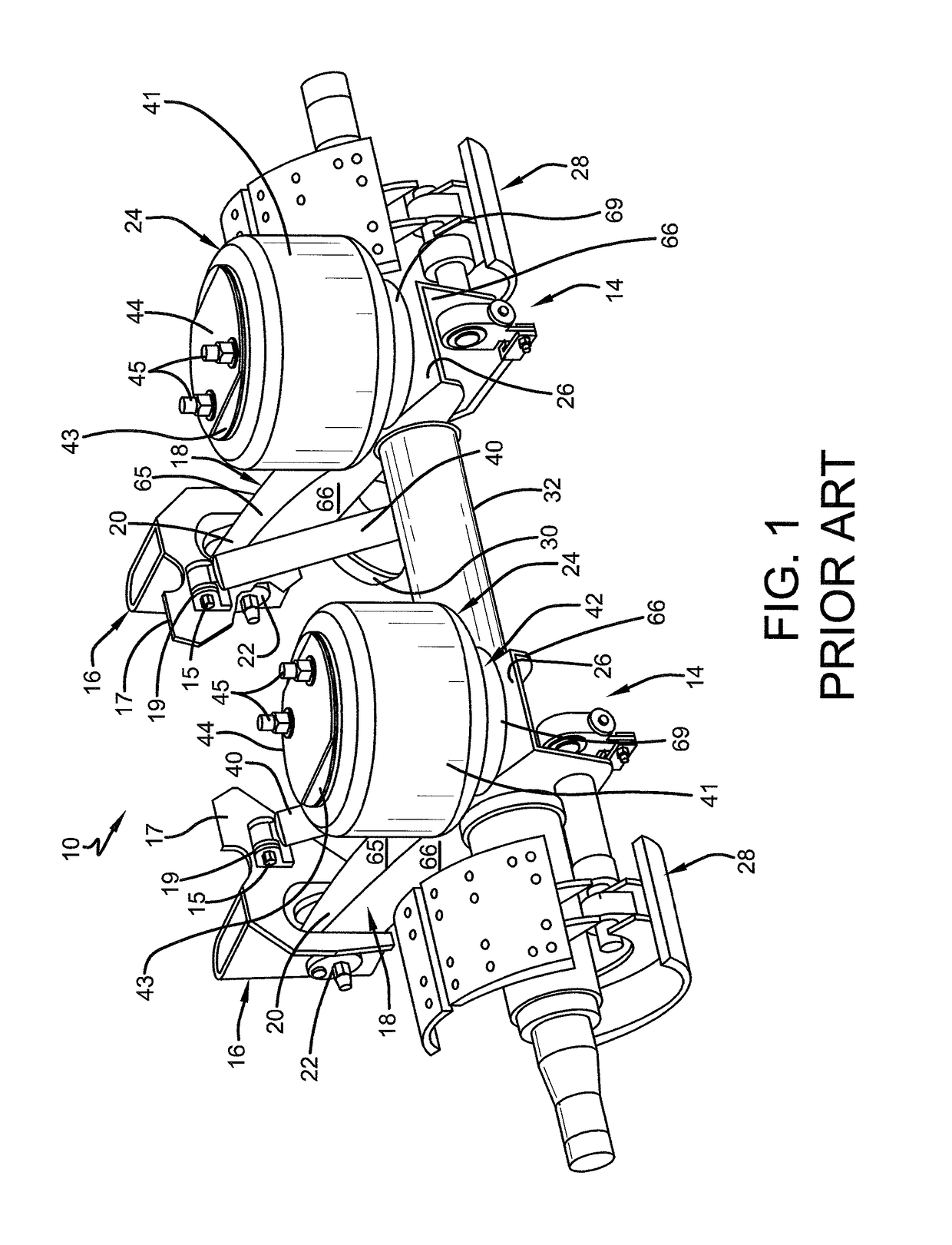
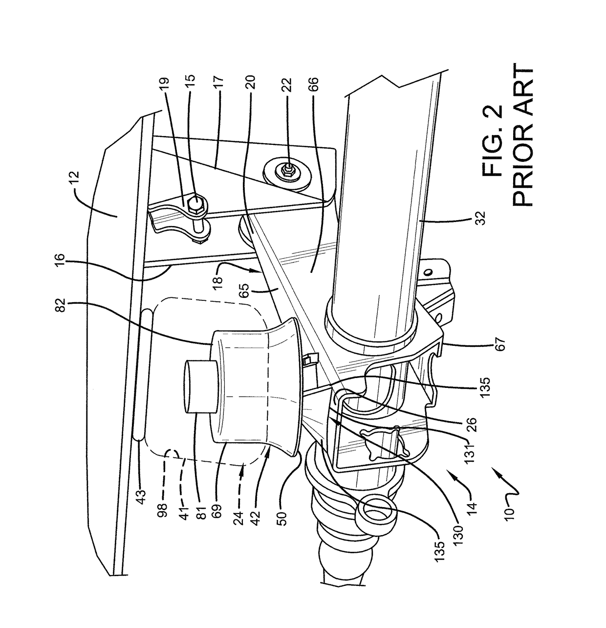
[0036]In order to better understand the environment in which the air spring with damping characteristics for a heavy-duty vehicle of the present invention is utilized, a trailing arm overslung beam-type air-ride axle / suspension system that incorporates a prior art air spring 24, is indicated generally at 10, is shown in FIGS. 1 and 2, and now will be described in detail below.

[0037]It should be noted that axle / suspension system 10 is typically mounted on a pair of longitudinally-extending spaced-apart main members 12 (FIG. 2, only one shown) of a heavy-duty vehicle, which is generally representative of various types of frames used for heavy-duty vehicles, including primary frames that do not support a subframe and primary frames and / or floor structures that do support a subframe. For primary frames and / or floor structures that do support a subframe, the subframe can be non-movable or movable, the latter being commonly referred to as a slider box. Because axle / suspension system 10 ge...


PUM


Abstract

An air spring with damping characteristics for a suspension assembly of a heavy-duty vehicle includes a bellows and a piston. The bellows includes a bellows chamber. The bellows is attached to a main member of the heavy-duty vehicle and to the piston. The piston includes an open bottom that is sealingly closed by a disc attached to the open bottom. The piston and the disc define a piston chamber. The piston is mounted on the suspension assembly of the heavy-duty vehicle. The bellows chamber and the piston chamber are in fluid communication with each other via at least one opening, wherein airflow between the bellows chamber and the piston chamber provides damping to the suspension assembly of the heavy-duty vehicle.

Description

CROSS-REFERENCE TO RELATED APPLICATION[0001]This application claims the benefit of U.S. Provisional Patent Application Ser. No. 62 / 159,528, filed May 11, 2015.BACKGROUND OF THE INVENTION[0002]Field of the Invention[0003]The invention relates generally to the art of axle / suspension systems for heavy-duty vehicles. More particularly, the invention relates to air-ride axle / suspension systems for heavy-duty vehicles, which utilize an air spring to cushion the ride of the vehicle. More specifically, the invention is directed to the conversion of a non-damping air spring to an air spring with damping characteristics, which is accomplished by sealing the non-damping air spring piston to create a piston chamber and providing fluid communication between the piston chamber and a bellows chamber of the air spring in order to provide damping characteristics to the air spring.[0004]Background Art[0005]The use of one or more air-ride trailing and leading arm rigid beam-type axle / suspension system...

Claims


Application Information

Patent Timeline
Patent Type & Authority Patents(United States)
IPC IPC(8): B60G15/12F16F9/04F16F9/05B60G11/27F16J3/06
CPCF16F9/057F16J3/06B60G15/12B60G11/27F16F9/049B60G2202/152B60G2202/32B60G2206/424B60G2206/911B60G2300/02B60G2300/026F16F9/0409F16F9/0454
Inventor KEELER, MICHAEL J.ZAWACKI, JEFF R.WESTNEDGE, ANDREW J.RAMUS, JASON M.ANDREASEN, JACOBGIAMATI, NICHOLAS J.
Owner HENDRICKSON USA L L C
Why Eureka
Try Eureka