
Snap fit assembly for a ruggedized multi-section structure with selective embrittlement or case hardening

a multi-section structure and selective embrittlement technology, applied in the direction of heat treatment equipment, manufacturing tools, furnaces, etc., can solve the problems of affecting the geometry of the interface, affecting the metallurgical properties, and compromising fragmentation performance, so as to avoid the use of welding and strong coupling force

Active Publication Date: 2017-08-22
THE UNITED STATES OF AMERICA AS REPRESENTED BY THE SECRETARY OF THE NAVY
View PDF1 Cites 6 Cited by
  • Summary
  • Abstract
  • Description
  • Claims
  • Application Information

AI Technical Summary

Benefits of technology

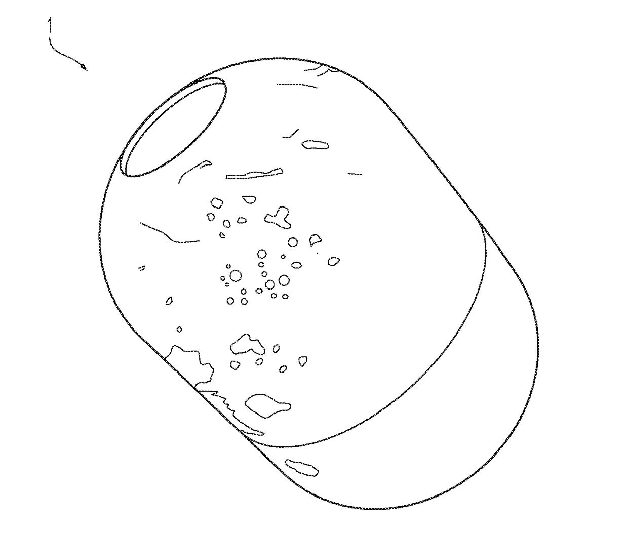
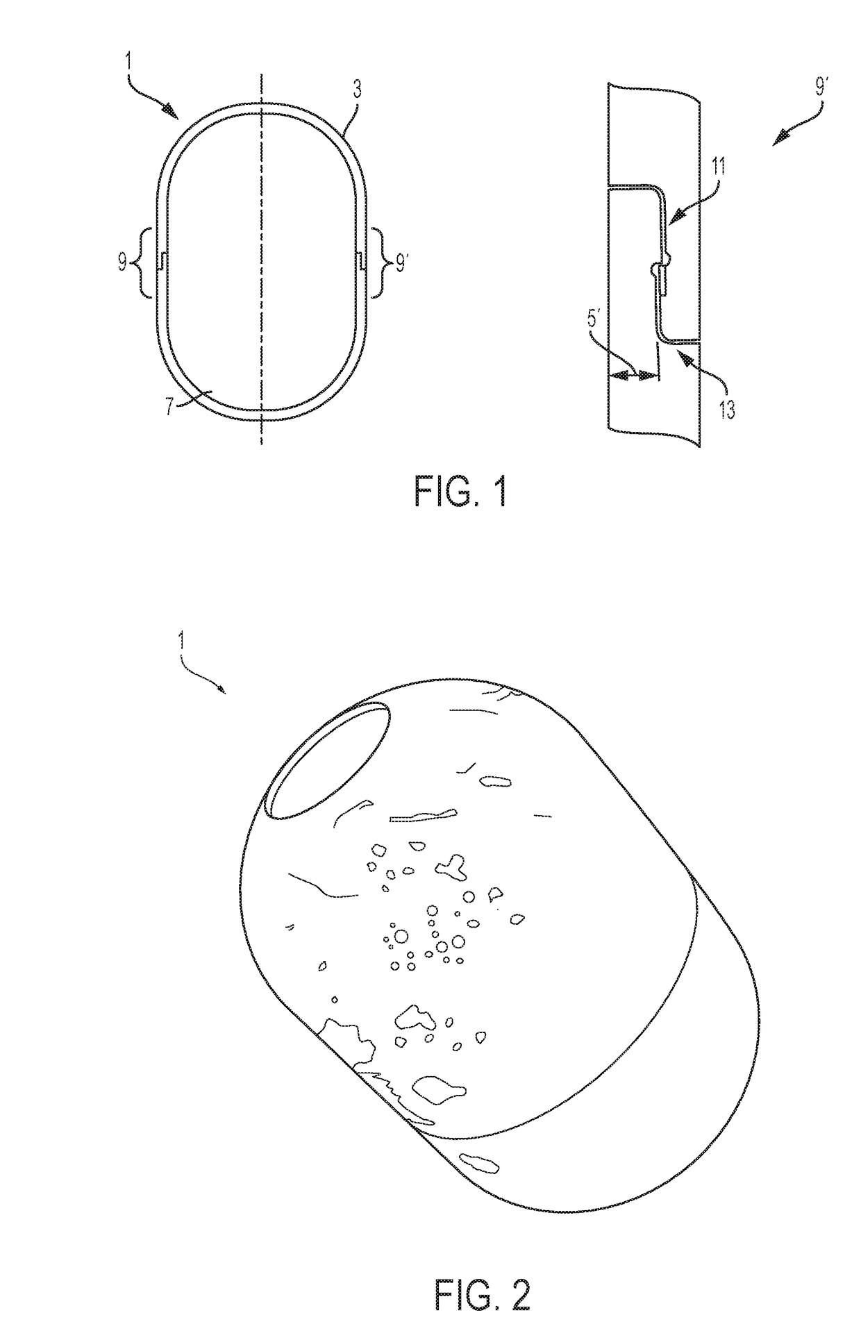
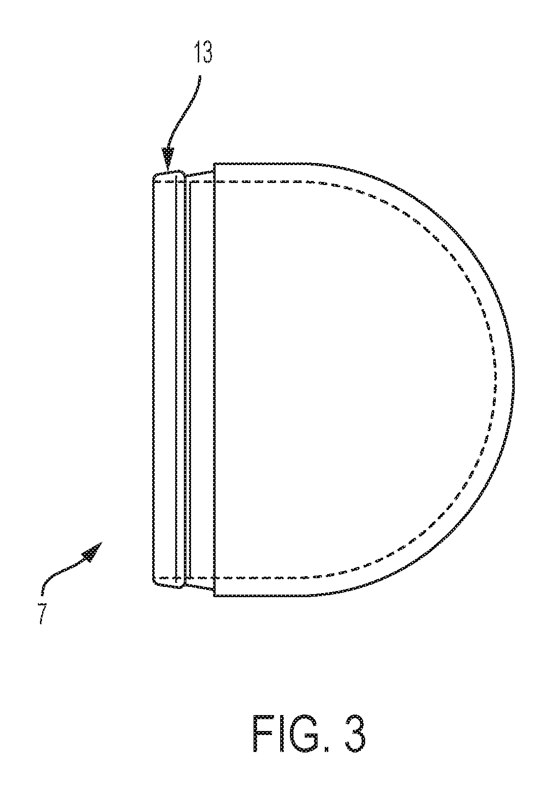
This patent is about a new way to join two parts together that doesn't require welding or other permanent joining methods like adhesive bonding. The invention also focuses on creating a structure that can be easily disassembled in a desired pattern. The design uses a snap-fit interlocking structure that allows for strong coupling and efficient production. It also allows for rotation between parts. The enclosure or structure has increased fragmentation capacity while still maintaining sufficient material properties to withstand impacts. The invention includes an interlocking structure that aligns with the desired pattern of fragmentation. The thickness of the parts can be different, and in some cases, one part can be thinner than another.

Problems solved by technology

Welding can result in altering the metallurgical properties to the extent that fragmentation performance is compromised.
Additionally, the geometry of the interface is affected by welding and difficult to control.
Welding after explosive loading is unsafe.
Threading the enclosure around an explosive load is undesired due to safety and production concerns.
Threads provide the opportunity to initiate stray explosive material with friction generated heat and are generally considered bad practice for energetic production.
However, it was not able to withstand rough handling testing believed required for various applications.

Method used


Image

  • Snap fit assembly for a ruggedized multi-section structure with selective embrittlement or case hardening
  • Snap fit assembly for a ruggedized multi-section structure with selective embrittlement or case hardening
  • Snap fit assembly for a ruggedized multi-section structure with selective embrittlement or case hardening

Examples


Embodiment Construction

of fragmentation device 100, 100′ may include a hardness value at outermost depth 130 of body 101, 101′ of 65-70 Rockwell C and, more particularly, a hardness value of 65.3-67.1 Rockwell C. However, as the distance from outermost depth 130 increases toward intermediate depth 132, the hardness of body 101, 101′ decreases to a hardness value of 40-60 Rockwell C and, more particularly, 41.6-59.9 Rockwell C. In this way, intermediate depth 132 has more ductility than outermost depth 130 of body 101, 101′. However, by increasing the carbon content at outermost depth 130, the hardness at outermost depth 130 also increases and brittle fracture may occur more easily at each valley 106, 106′ such that increased fragmentation occurs in fragmentation device 100, 100′.

[0072]FIG. 11 shows a graphical representation of exemplary hardness values of a surface of another exemplary embodiment of the present disclosure. As show in Example 2 of FIG. 11, body 101, 101′ of Example 2 may be carburized to ...


PUM

PropertyMeasurementUnit
thicknessaaaaaaaaaa
thicknessaaaaaaaaaa
thicknessaaaaaaaaaa

Abstract

Apparatus and methods associated with an enclosure or structure including two sections that are adapted with a snap-fit interlocking structure. Various embodiments of the enclosure or structures are formed with various case hardening or embrittlement processes to increase embrittlement or hardness of the enclosure or structure so as to create a structure or enclosure which has a desired fragmentation capacity while still maintaining sufficient material properties to permit snap-fit insertion of one section into another section and withstand substantial impacts. Embodiments also provide an interlocking structure that minimizes differences in fragmentation or fracturing capacity as contrasted with other portions of the structure or enclosure. An embodiment of the invention includes an enclosure where one section of the enclosure or structure has a first thickness and the second section has a second thickness, wherein the first and second thicknesses are different. In some embodiments, one section is thinner than another section.

Description

CROSS-REFERENCE TO RELATED APPLICATION[0001]The present application claims priority to U.S. Provisional Patent Application Ser. No. 62 / 206,831, filed Aug. 18, 2015, entitled “SNAP FIT ASSEMBLY FOR A RUGGEDIZED MULTI-SECTION STRUCTURE WITH SELECTIVE EMBRITTLEMENT OR CASE HARDENING,” and is related to U.S. patent application Ser. No. 14 / 689,696, filed Apr. 17, 2015, entitled “FRAGMENTATION DEVICE WITH INCREASED SURFACE HARDNESS AND A METHOD OF PRODUCING THE SAME”, the complete disclosures of which are expressly incorporated by reference herein.STATEMENT REGARDING FEDERALLY SPONSORED RESEARCH OR DEVELOPMENT[0002]The invention described herein includes contributions by one or more employees of the Department of the Navy made in the performance of official duties and may be manufactured, used and licensed by or for the United States Government without payment of any royalties thereon. This invention (Navy Case 200,274) is assigned to the United States Government and is available for lice...

Claims


Application Information

Patent Timeline
Patent Type & Authority Patents(United States)
IPC IPC(8): F42B12/22C21D9/16C21D1/06C23C8/22C23C8/04F42B12/20F42B12/28F42B33/02F42B12/24
CPCC21D9/16C21D1/06C23C8/04C23C8/22F42B12/207F42B12/22F42B12/28F42B33/02F42B12/24
Inventor GWALTNEY, JOSHALLISON, LUCASSCHEID, ERICDESHPANDE, NISHKAMRAJWOLF, ALANSCHISLER, EDDIE
Owner THE UNITED STATES OF AMERICA AS REPRESENTED BY THE SECRETARY OF THE NAVY
Learn More