Thermally-assisted magnetic recording head including a main pole and a plasmon generator

Active Publication Date: 2017-08-22
HEADWAY TECH INC
View PDF21 Cites 8 Cited by
  • Summary
  • Abstract
  • Description
  • Claims
  • Application Information

AI Technical Summary

Benefits of technology

The present invention provides a thermally-assisted magnetic recording head and its manufacturing method that improves the reliability of the plasmon generator, aligns the end face of the plasmon generator with the end face of the main pole, and allows for a desired sizing of the width of the main pole without limitations whatsoever. The plasmon generator includes a first material portion and a second material portion formed of different materials, which improves its reliability. The space between the first and second surrounding layer end faces, in which at least part of the first end face portion lies, can be adjusted by the width of the portions of the first and second gap film end faces located between the first surrounding layer end face and the second surrounding layer end face, which allows for precise alignment of the near-field light generating surface and the first end face portion with each other, and also allows for a desired sizing of the width of the first end face portion without limitations imposed by the width of the near-field light generating surface.

Problems solved by technology

Making the magnetic fine particles smaller, however, disadvantageously reduces the thermal stability of magnetization of the magnetic fine particles.
However, increasing the anisotropic energy of the magnetic fine particles leads to an increase in coercivity of the recording medium, and this makes it difficult to perform data writing with existing magnetic heads.
This results in the problem of deformation or breakage of the plasmon generator, thus shortening the life of the thermally-assisted magnetic recording head.
When employing this technique, however, any attempts to reduce the track width would result in a reduction in the width of the end face of the main pole, and this would cause the main pole to become unable to pass much magnetic flux and thus unable to produce a write magnetic field of sufficient magnitude from its end face.
A further problem with the aforementioned technique is that it is difficult to permit a desired sizing of the width of the end face of the main pole without limitations imposed by the width of the end face of the plasmon generator.

Method used


Image

  • Thermally-assisted magnetic recording head including a main pole and a plasmon generator
  • Thermally-assisted magnetic recording head including a main pole and a plasmon generator
  • Thermally-assisted magnetic recording head including a main pole and a plasmon generator

Examples


first embodiment

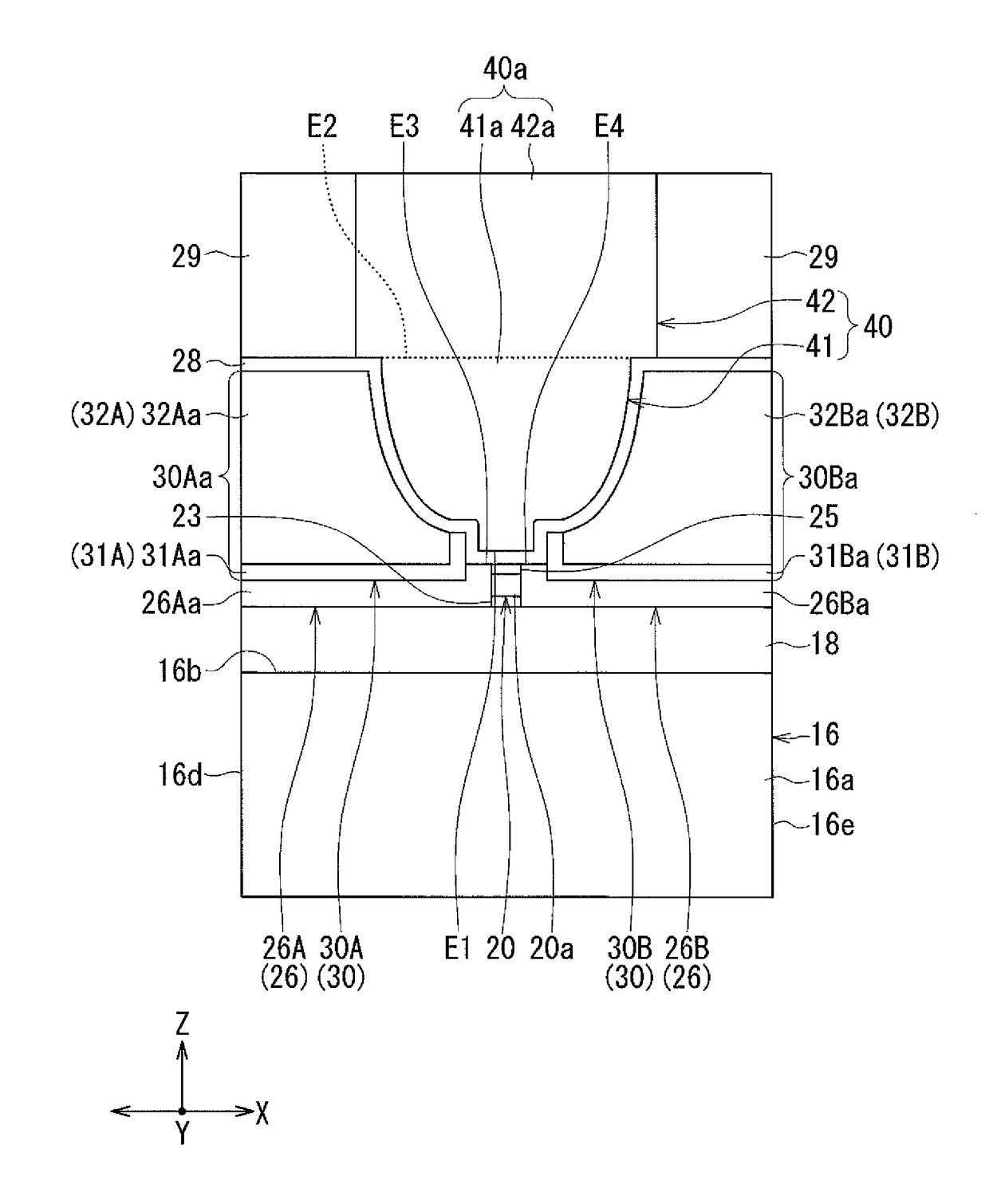
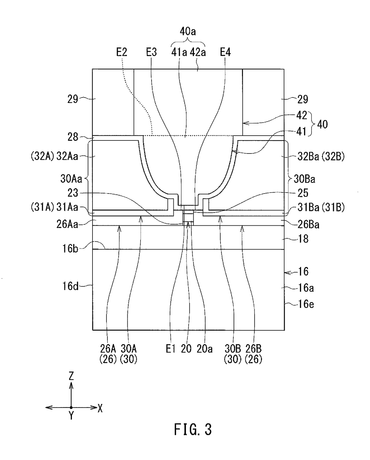
[0078]Preferred embodiments of the present invention will now be described in detail with reference to the drawings. First, reference is made to FIG. 3 to FIG. 9 to describe the configuration of a thermally-assisted magnetic recording head according to a first embodiment of the invention. FIG. 3 is a front view showing the main part of the thermally-assisted magnetic recording head. FIG. 4 is a cross-sectional view showing the main part of the thermally-assisted magnetic recording head. FIG. 5 is a plan view showing a main pole, a surrounding layer, and a first heat sink. FIG. 6 is a cross-sectional view showing the configuration of the thermally-assisted magnetic recording head. FIG. 7 is a front view showing the medium facing surface of the thermally-assisted magnetic recording head. FIG. 8 is a plan view showing a first layer of a coil of the present embodiment. FIG. 9 is a plan view showing a second layer of the coil of the present embodiment.

[0079]The thermally-assisted magneti...

second embodiment

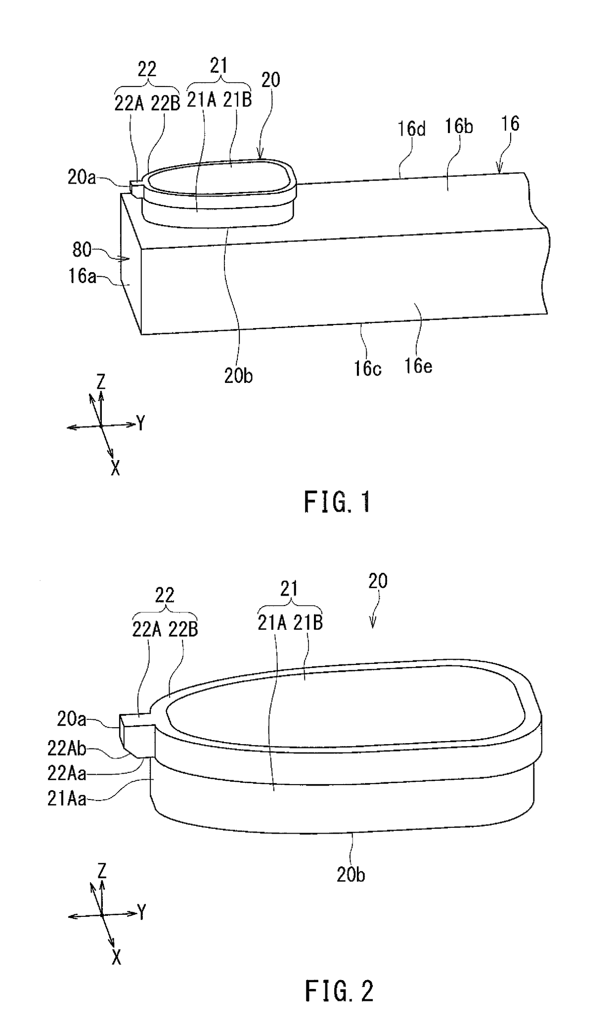
[0182]A thermally-assisted magnetic recording head according to a second embodiment of the invention will now be described with reference to FIG. 24 and FIG. 25. FIG. 24 is a perspective view showing a plasmon generator of the present embodiment. FIG. 25 is a cross-sectional view showing the main part of the thermally-assisted magnetic recording head according to the present embodiment.

[0183]The thermally-assisted magnetic recording head according to the present embodiment is configured differently than in the first embodiment in the following ways. In the present embodiment, the dielectric layer 23 of the first embodiment is omitted. Further, the narrow portion 22A of the second material portion 22 of the plasmon generator 20 does not have the connecting surface 22Ab described in relation to the first embodiment. The bottom surface 22Aa of the narrow portion 22A is connected to the near-field light generating surface 20a. Further, the front end portion 21Aa of the first layer porti...

third embodiment

[0186]A thermally-assisted magnetic recording head according to a third embodiment of the invention will now be described with reference to FIG. 26 and FIG. 27. FIG. 26 is a perspective view showing a plasmon generator of the present embodiment. FIG. 27 is a cross-sectional view showing the main part of the thermally-assisted magnetic recording head according to the present embodiment.

[0187]The thermally-assisted magnetic recording head according to the present embodiment is configured differently than in the second embodiment in the following ways. In the present embodiment, the entirety of the first material portion 21 of the plasmon generator 20 lies inside the ring portion 22B of the first material portion 22. In the present embodiment, the first layer portion 21A and the second layer portion 21B are omitted from the first material portion 21. Further, the cladding layer 18 does not have the receiving section 18a. The entirety of the plasmon generator 20 lies on the cladding lay...


PUM


Abstract

A thermally-assisted magnetic recording head includes a main pole and a plasmon generator. The plasmon generator includes a first material portion and a second material portion formed of different materials. The first material portion is located away from the medium facing surface. The second material portion includes a near-field light generating surface. The main pole has a front end face including a first end face portion and a second end face portion. The near-field light generating surface, the first end face portion and the second end face portion are arranged in this order along the direction of travel of a recording medium.

Description

BACKGROUND OF THE INVENTION[0001]1. Field of the Invention[0002]The present invention relates to a thermally-assisted magnetic recording head for use in thermally-assisted magnetic recording to write data on a recording medium with the coercivity thereof lowered by irradiating the recording medium with near-field light.[0003]2. Description of the Related Art[0004]Recently, magnetic recording devices such as magnetic disk drives have been improved in recording density, and thin-film magnetic heads and recording media of improved performance have been demanded accordingly. Among the thin-film magnetic heads, a composite thin-film magnetic head has been used widely. The composite thin-film magnetic head has such a structure that a read head unit including a magnetoresistive element (hereinafter, also referred to as MR element) for reading and a write head unit including an induction-type electromagnetic transducer for writing are stacked on a substrate. In a magnetic disk drive, the th...

Claims


Application Information

Patent Timeline
IPC IPC(8): G11B11/00G11B5/48G11B5/127G11B5/00G11B5/31G11B5/60G11B7/1387
CPCG11B5/4866G11B5/1272G11B2005/0021G11B2005/0005G11B5/6088G11B2005/001G11B5/314G11B7/1387
Inventor SASAKI, YOSHITAKAITO, HIROYUKITANEMURA, SHIGEKIMAMIYA, HIDEOTOMITA, SEIICHIROARAKI, HIRONORI
Owner HEADWAY TECH INC
Why Eureka
Try Eureka