
Apparatus of high frequency plasma

Active Publication Date: 2017-08-22
INST NUCLEAR ENERGY RES ROCAEC
View PDF3 Cites 2 Cited by
  • Summary
  • Abstract
  • Description
  • Claims
  • Application Information

AI Technical Summary

Benefits of technology

The present invention relates to a high-frequency plasma apparatus that can generate uniform large-area plasma in a wider operation window, while offering better flexibility. The patent describes a technique involving the simultaneous launch of two standing waves with different temporal and spatial patterns to improve discharge uniformity. The high-frequency plasma apparatus can be operated in both continuous-wave and pulsed modes, and can easily adjust to changes in operating parameters. The main technical effects of this invention include improved plasma uniformity and flexibility in operating modes.

Problems solved by technology

However, due to the capacitive nature of CCP, the deposition of device-grade thin films at a higher rate cannot be achieved by simply raising the discharge power because a higher discharge power would result in more severe ion bombardment, which would lead to the deterioration of film quality.
Nevertheless, the combination of higher frequency and larger electrode would lead to the problem of non-uniform plasma discharge caused by the standing wave effect.
Nevertheless, this technique can only be operated in pulsed mode rather than in continuous-wave mode that is more commonly used for PECVD.
In pulsed mode, the standing waves must be alternately generated in terms of time, such that unnecessary limitations for deposition processes might be imposed.
For instance, for thin film silicon solar cell, it has been reported that pulsed mode results in not only a lower deposition rate of the silicon thin film, but also a poorer performance of conversion efficiency compared with continuous-wave mode.
As stated above, though a number of techniques in the art, such as the aforesaid resorts, can be applied to resolve the problem caused by the standing wave effect, yet the common shortcomings among these techniques still exist, which leads to the problem that they are only capable of generating uniform discharge in a narrow operation window.

Method used


Image

  • Apparatus of high frequency plasma
  • Apparatus of high frequency plasma
  • Apparatus of high frequency plasma

Examples


Embodiment Construction

[0033]The invention disclosed herein is directed to an apparatus of high frequency plasma. In the following description, numerous details are set forth in order to provide a thorough understanding of the present invention. It will be appreciated by one skilled in the art that variations of these specific details are possible while still achieving the results of the present invention. In other instance, well-known components are not described in detail in order not to unnecessarily obscure the present invention.

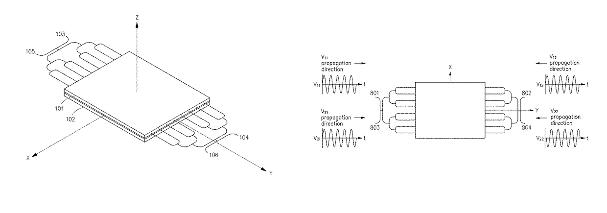
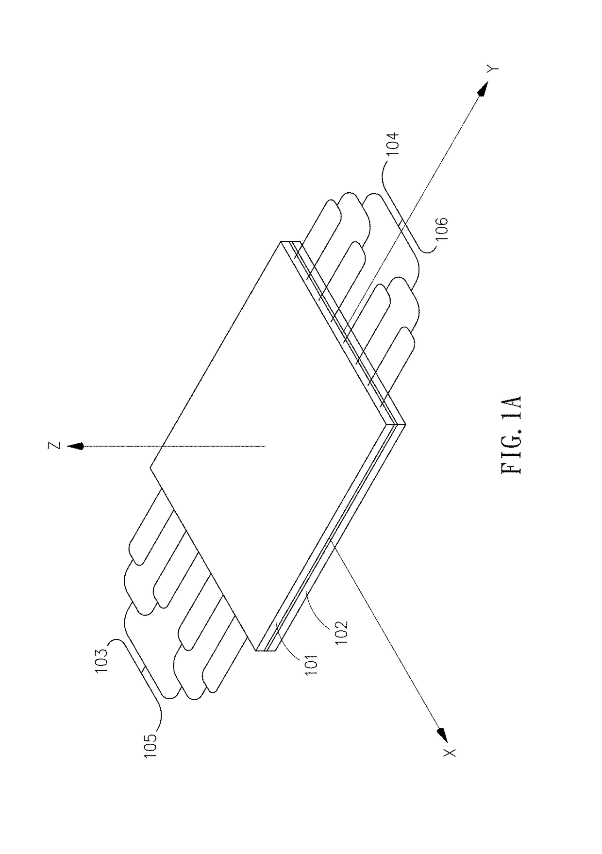
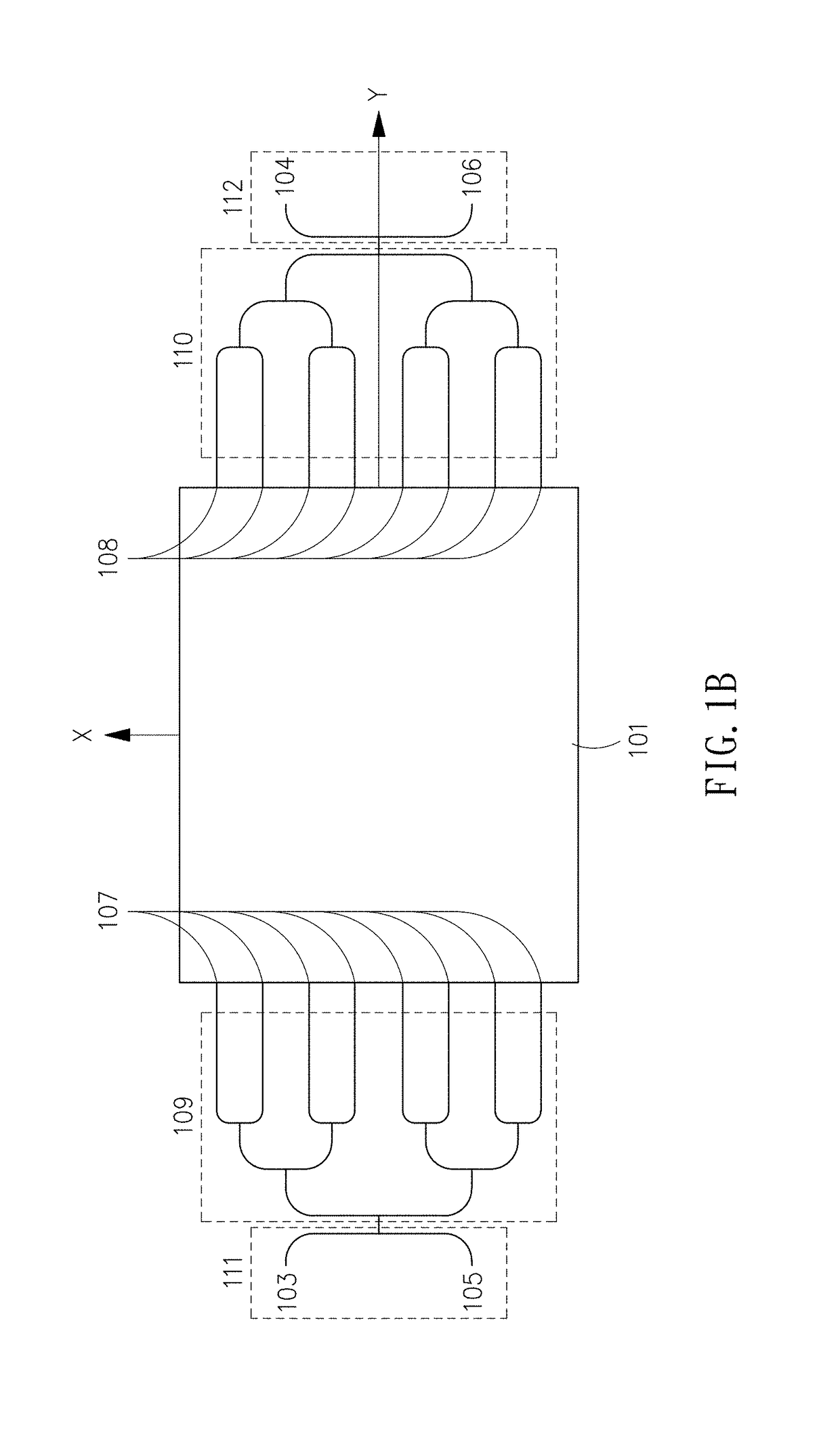
[0034]Refer now to FIG. 1A and FIG. 1B; where FIG. 1A is a schematic view of an embodiment of the high frequency plasma apparatus in accordance with the present invention, and FIG. 1B is a top view of the first electrode of FIG. 1A.

[0035]As shown in FIG. 1A and FIG. 1B, this embodiment includes a first electrode 101, a second electrode 102, a plurality of feed points 103˜108, two power dividers 109, 110 and two power combiners 111, 112.

[0036]Referring now to FIG. 1A, the first...


PUM


Abstract

A high frequency plasma apparatus includes a reaction chamber, a first electrode, a second electrode, and a plurality of feed points located at one of the two electrodes at least. The feed points are used to simultaneously generate a first standing wave and a second standing wave, with different temporal and spatial patterns. By adjusting amplitudes of the two standing waves and the temporal and spatial phase differences between the two standing waves appropriately, plasma uniformity of the high frequency plasma apparatus can be effectively improved.

Description

CROSS REFERENCE TO RELATED APPLICATION[0001]This application claims the benefit of Taiwan Patent Application Serial No. 105114913, filed May 13, 2016, the subject matter of which is incorporated herein by reference.BACKGROUND OF INVENTION[0002]1. Field of the Invention[0003]The invention relates to a high frequency plasma apparatus, and more particularly to the high frequency plasma apparatus that utilizes the superposition of two standing waves, simultaneously generated but with different temporal and spatial patterns, so as to effectively improve the uniformity of plasma discharge.[0004]2. Description of the Prior Art[0005]Plasma-enhanced chemical vapor deposition (PECVD) has been widely applied to various hi-tech industries, such as semiconductor, flat display panel and solar cell industries. Currently, capacitive coupled plasma (CCP), typically operated at 13.56 MHz, remains the mainstream plasma source for PECVD. In order to further reduce the production costs by improving the ...

Claims


Application Information

Patent Timeline
IPC IPC(8): H01J7/24H05B31/26H01J37/32
CPCH01J37/32128H01J37/32532H01J2237/3321H01J2237/3323H01J2237/3325H01J37/32091H01J37/32541H01J37/32577
Inventor CHEN, HSIN-LIANGHSIEH, CHENG-CHANGLIN, DENG-LAINTSENG, CHING-PEIYANG, MING-CHUNG
Owner INST NUCLEAR ENERGY RES ROCAEC
Features
  • Generate Ideas
  • Intellectual Property
  • Life Sciences
  • Materials
  • Tech Scout
  • Unparalleled Data Quality
  • Higher Quality Content
  • 60% Fewer Hallucinations
Learn More