Composition for nanoimprint and nanoimprint pattern forming method
a technology of nano-imprints and patterns, applied in the field of composition of nano-imprints and nano-imprint pattern forming methods, can solve problems such as deterioration of pattern transferability, and achieve the effect of excellent mold release properties
Active Publication Date: 2017-08-29
TOKYO OHKA KOGYO CO LTD
View PDF6 Cites 0 Cited by
- Summary
- Abstract
- Description
- Claims
- Application Information
AI Technical Summary
Benefits of technology
[0018]According to the present invention, it is possible to provide a composition for nanoimprint having excellent mold releasing properties and a nanoimprint pattern forming method using the composition for nanoimprint.
Problems solved by technology
When the coating properties are degraded, the film thickness of the composition for nanoimprint, which is applied to the substrate, becomes uneven and this leads to deterioration of pattern transferability at the time when a mold is pressed.
Method used
View moreImage
Smart ImageViewing Examples

Examples
example 1
on 1 for Nanoimprint
[0193]1 part by mass of the following compound (C)-1 and 1 part by mass of the following polymeric compound (F)-1 (30% PGMEA supply) were mixed with 100 parts by mass of a resin component obtained by mixing 3 parts by mass of the following polymeric compound (A)-1 with 97 parts by mass of the following polymeric compound (B1)-1, thereby preparing a composition 1 for nanoimprint.
[0194]
Login to View More PUM
| Property | Measurement | Unit |
|---|---|---|
| boiling point | aaaaa | aaaaa |
| boiling point | aaaaa | aaaaa |
| boiling point | aaaaa | aaaaa |
Abstract
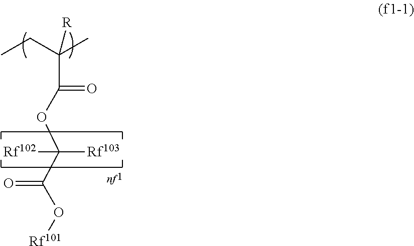
A composition for nanoimprinting including a siloxane polymer which includes a polymerizable group polymerized by irradiation with light; a polymerization initiator; and a fluorine-containing polymeric compound in which the fluorine-containing polymeric compound has a constituent unit represented by the following formula (f1-1) in which R represents a hydrogen atom, an alkyl group having 1 to 5 carbon atoms, or a halogenated alkyl group having 1 to 5 carbon atoms, Rf102 and Rf103 each independently represent a hydrogen atom, a halogen atom, an alkyl group having 1 to 5 carbon atoms, or a halogenated alkyl group having 1 to 5 carbon atoms, Rf102 and Rf103 may be the same as or different from each other, nf1 represents an integer of 1 to 5, and Rf101 represents an organic group including a fluorine atom.
Description
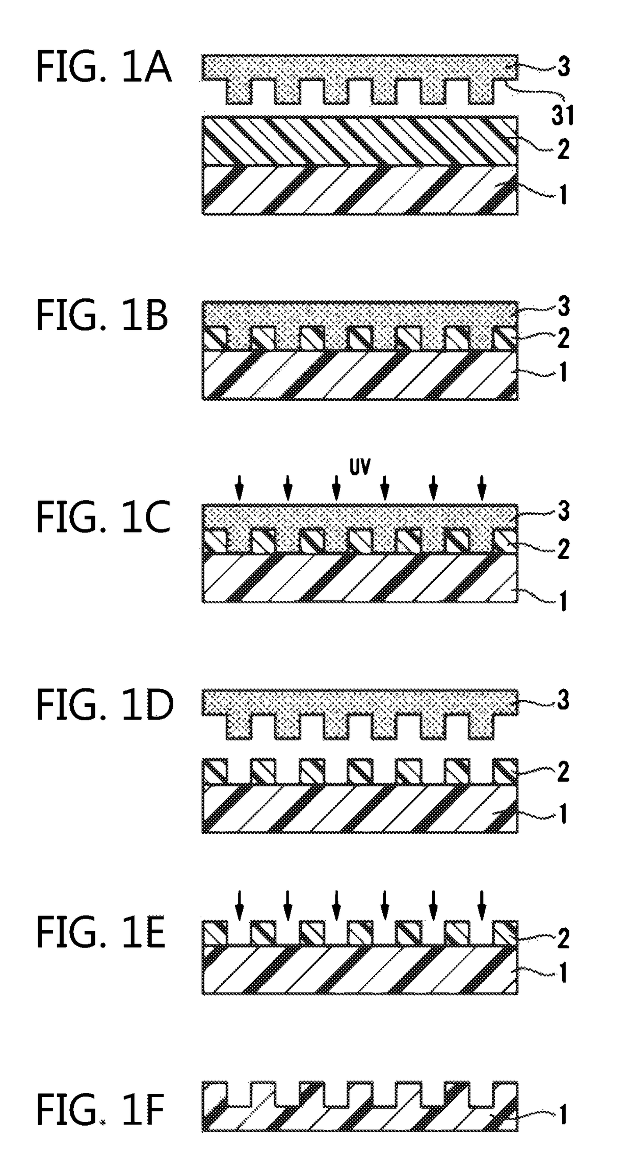
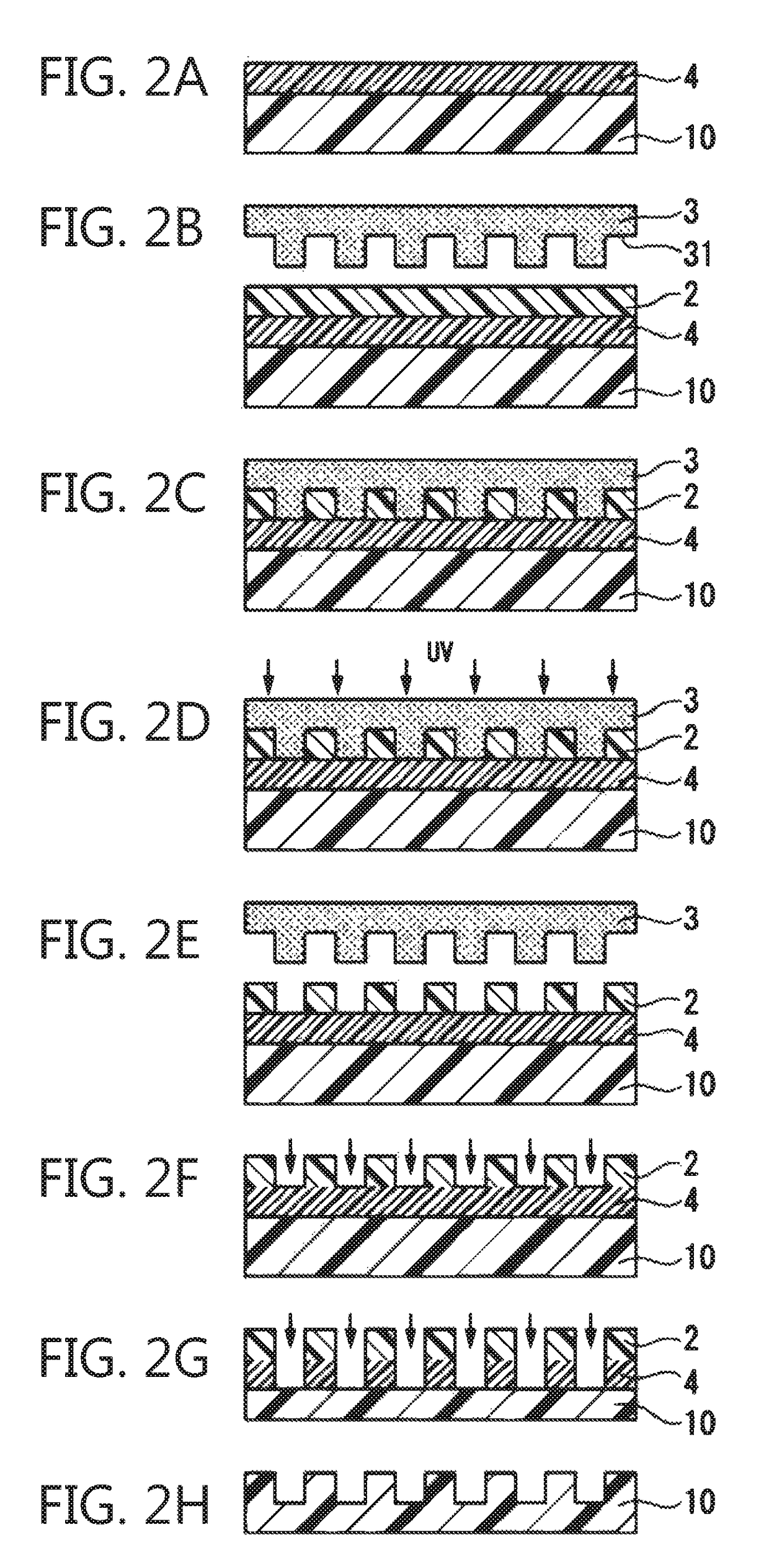
BACKGROUND OF THE INVENTION[0001]Field of the Invention[0002]The present invention relates to a composition for nanoimprint and a nanoimprint pattern forming method.[0003]Priority is claimed on Japanese Patent Application No. 2015-083209, filed on Apr. 15, 2015, the contents of which are incorporated herein by reference.[0004]Description of Related Art[0005]A lithography technology is a core technology of a semiconductor device process, and further miniaturization of wiring has been promoted with high integration of a semiconductor integrated circuit (IC) in recent years. As the miniaturization method, a method of shortening the wavelength of a light source by means of using a light source having a shorter wavelength such as a KrF excimer laser, an ArF excimer laser, an F2 laser, extreme ultraviolet light (EUV), electron beams (EB), or X-rays or a method of making the diameter of a numerical aperture (NA) of a lens of an exposure device large (making the NA large) is typically exemp...
Claims
Login to View More Application Information
Patent Timeline
 Patent Type & Authority Patents(United States)
IPC IPC(8): C08F2/46C08G61/04C09D183/04G03F7/004G03F7/038G03F7/075G03F7/00
CPCG03F7/0002C09D183/04G03F7/0046G03F7/0388G03F7/0757C09D183/06C08G77/18C08G77/20C08L83/06C08L33/16G03F7/004G03F7/028B29C59/02G03F7/20
Inventor KONNO, KENRI
Owner TOKYO OHKA KOGYO CO LTD