Bicycle rear derailleur with a damper assembly

a technology of derailleur and damper assembly, which is applied in the direction of chain/belt transmission, vehicle components, vehicle transmission, etc., can solve the problems of increasing the risk of a subsequent reduction of the chain tensioning below the necessary level, and reducing the chain tensioning with unwanted slackness

Active Publication Date: 2017-09-05
SRAM CORPORATION
View PDF13 Cites 22 Cited by
  • Summary
  • Abstract
  • Description
  • Claims
  • Application Information

AI Technical Summary

Benefits of technology

[0010]One object of the present invention is to provide a bicycle rear derailleur which is mechanically simple.
[0011]Another object of the present invention is to provide a bicycle rear derailleur which may be easily assembled during manufacturing and provides the correct damping force with high certainty.
[0013]Another object of the present invention is to provide a bicycle rear derailleur which has favorable damping characteristics.
[0019]The damping spring may be coupled with the movable member for supporting the spring engagement portion against rotation with respect to the movable member. The wedge member may eliminate the rotational play between the damping spring and the moveable member. The damping spring may include a spring retaining portion extending radially outwardly with respect to the spring engagement portion for coupling the spring engagement portion with the movable member. The spring engagement portion may have a free end. At least one wedge member may be operatively disposed between the spring retaining portion and the movable member. The wedge member may bias the spring retaining portion against a first abutment surface of the movable member. Further, the wedge member may be located between the spring retaining portion and a second abutment surface opposite to the first abutment surface.
[0022]The spring engagement portion of the damping spring may wrap around the outer circumferential counter engagement surface. The spring engagement portion may wrap more tightly about the outer circumferential counter engagement surface when the chain guide assembly rotates in the second rotational direction to increase the frictional force. The spring engagement portion may wrap more loosely about the outer circumferential counter engagement surface when the chain guide assembly rotates in the second rotational direction to decrease the frictional force.

Problems solved by technology

For example, when riding on uneven surfaces, the derailleur and the chain are subjected to blows and vibrations which may act on the chain guide assembly in a rotational direction opposite to the “chain tensioning direction.” A rotation of the chain guide assembly in the direction opposite to this “chain tensioning direction” increases the tension of the tension spring acting on the chain guide assembly and directly results in a reduction of the chain tension or at least results in a greater risk of a subsequent reduction of the chain tensioning below a necessary level.
Negative effects may be a drop in the chain tensioning with unwanted slackness or “dangling” of the chain.
In a worst case, the chain may fall off the sprocket assembly.
However, for such an adjustment a tool is required and the question arises if an average rider has the necessary knowledge to adjust the damping force correctly.
Further, the exposed adjustment nut is not protected from undesired rotation which may result in undesired adjustment of the damping force.
Providing the cyclist with such a choice calls for a relatively high mechanical effort.

Method used


Image

  • Bicycle rear derailleur with a damper assembly
  • Bicycle rear derailleur with a damper assembly
  • Bicycle rear derailleur with a damper assembly

Examples


Embodiment Construction

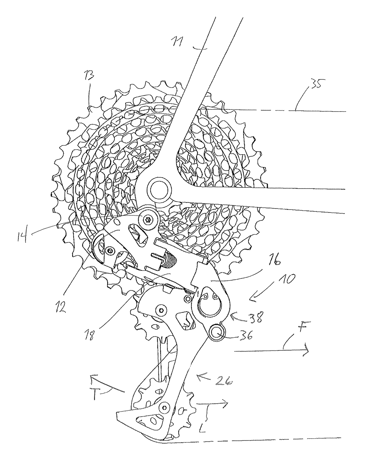
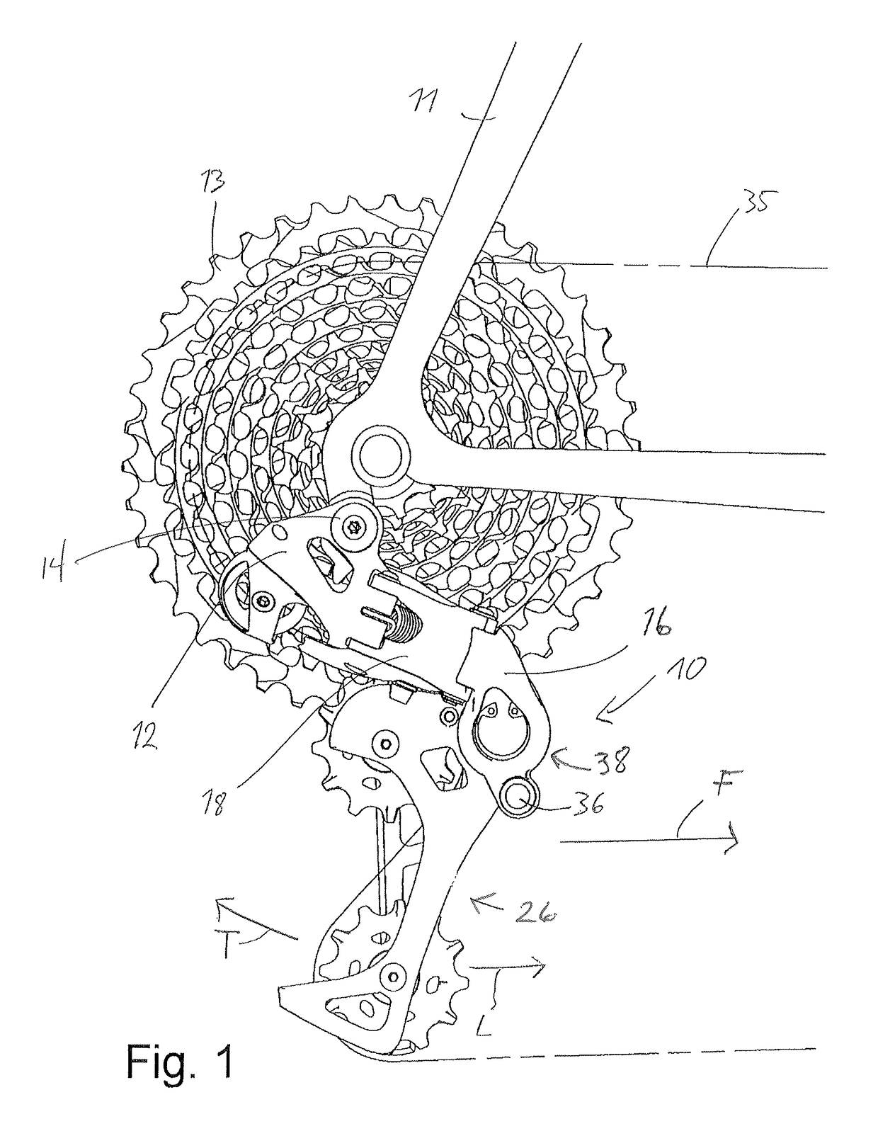
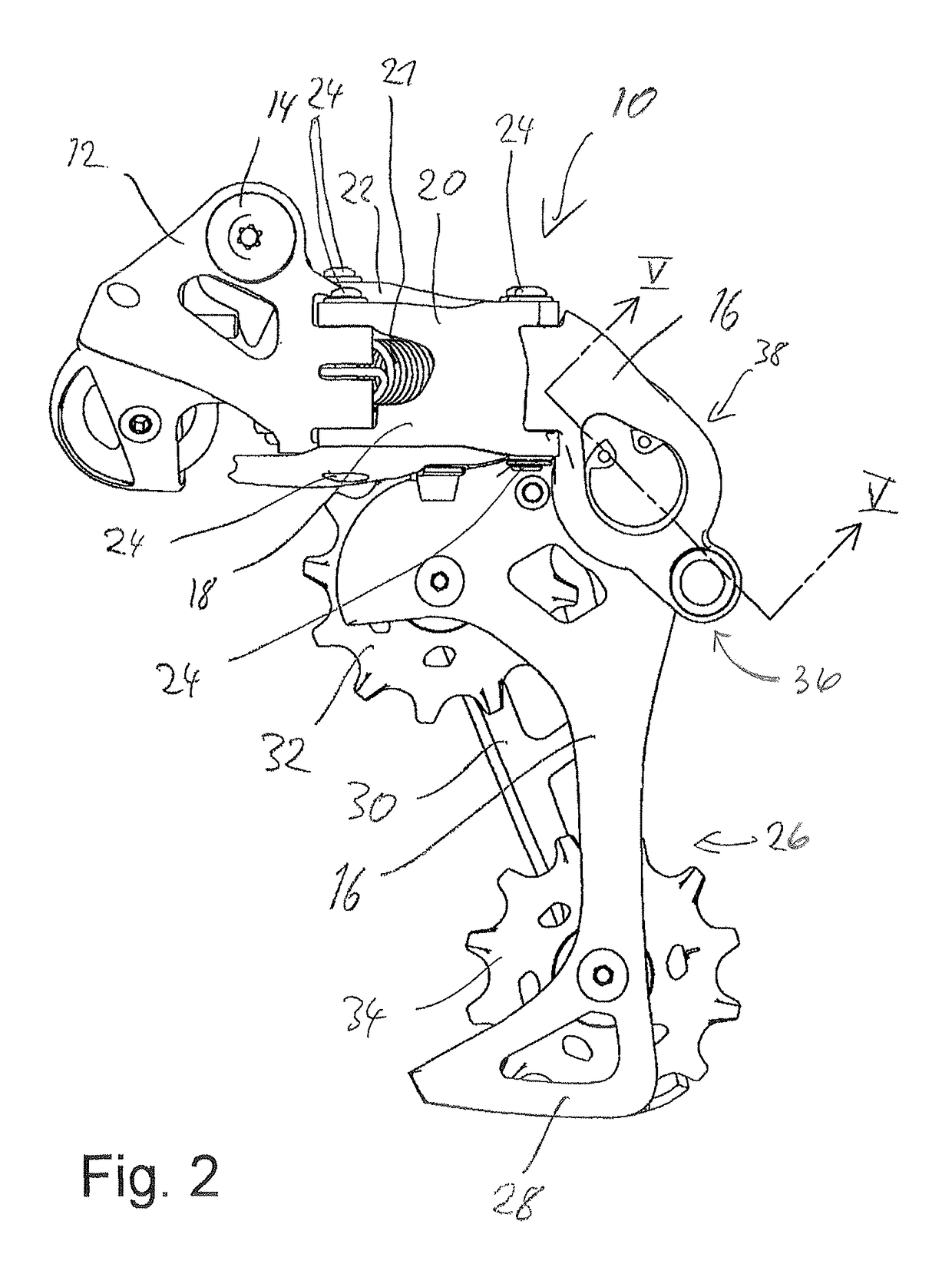
[0035]Several embodiments of the invention will herein by described with reference to the drawings. It will be understood that the drawings and description set out herein are provided for illustration only and do not limit the invention as defined by the claims appended hereto and any and all equivalence. For example, terms such as “first” and “second,”“upper” and “lower,” or “forward” and “rearward” are used for the sake of orientation and not as terms of limitation. Moreover, the terms preferably refer to the bicycle derailleur conventionally mounted to a bicycle and with the bicycle orientated for normal use unless otherwise indicated. For example, the front of an element would be that part of the element oriented / closest to the front of the bicycle.

[0036]Looking to FIGS. 1-6, a bicycle derailleur 10 is shown according to one embodiment of the present invention. The bicycle derailleur 10 generally includes a base member 12, a movable member 16, a swing linkage 18, a chain guide a...


PUM


Abstract

A bicycle rear derailleur includes a base member mountable to a bicycle frame. A movable member is movably coupled to the base member. A chain guide assembly is rotatably connected to the movable member for rotation about a rotation axis. A biasing element is configured to bias the chain guide assembly for rotation in a first rotational direction with respect to the movable member. A damper assembly is operatively disposed between the chain guide assembly and the movable member to apply a damping force to the chain guide assembly when the chain guide assembly rotates in a second rotational direction opposite to the first rotational direction. The damper assembly includes a one-way roller clutch assembly disposed coaxially about the rotational axis and a friction unit extending circumferentially over a circumferential angle coaxially about the rotational axis.

Description

BACKGROUND OF THE INVENTION[0001]The present invention generally relates to bicycle rear derailleurs and more particularly to a bicycle rear derailleur with a damper assembly.[0002]As is known, a bicycle derailleur performs shifting operations by shifting the chain between a plurality of adjacent sprockets of a sprocket assembly of a bicycle. A further, also very important function of the derailleur is to ensure a sufficient chain tension. A bicycle derailleur is generally constructed in the following manner. A base member is mounted to the bicycle frame. Further, a movable member is movably connected to the base member and a chain guide assembly is movable connected to the movable member with respect to rotation about a rotational axis. The movable member is movable in the axial direction, to move the chain guide assembly between the sprockets of the sprocket assembly, so that the chain may be shifted from an initial sprocket to a target sprocket. The chain guide assembly is biased...

Claims


Application Information

Patent Timeline
Patent Type & Authority Patents(United States)
IPC IPC(8): B62M9/126B62M9/1248B62M9/16B62M9/128
CPCB62M9/126B62M9/128B62M9/1248B62M9/16
Inventor SHIPMAN, CHRISTOPHERJORDAN, BRIAN
Owner SRAM CORPORATION
Why Eureka
Try Eureka