
Power management system and power management method

a power management system and power management technology, applied in the field of power management systems, can solve the problems of inability to obtain a power source, inability to stably supply power to the measuring means and the communication means, and the amount of power generated by the off-grid power supply means such as photovoltaic cells is affected by weather, so as to shorten the transmission cycle of communication and shorten the measurement cycl

Active Publication Date: 2017-09-05
KYOCERA CORP
View PDF8 Cites 0 Cited by
  • Summary
  • Abstract
  • Description
  • Claims
  • Application Information

AI Technical Summary

Benefits of technology

[0027]In the third feature, the first power threshold is a first extended power threshold to be used for determining whether or not to extend a measurement cycle of the measuring means and a first shortened power threshold to be used for determining whether or not to shorten a measurement cycle of the measuring means. The second power threshold is a second extended power threshold to be used for determining whether or not to extend a transmission cycle of the communication means and a second shortened power threshold to be used for determining whether or not to shorten the transmission cycle of the communication means. The power management method comprises steps of: setting, as the first extended power threshold, a threshold smaller than the second extended power threshold, and setting, as the first shortened power threshold, a threshold smaller than the second shortened power threshold.

Problems solved by technology

There are some cases, though, where it is not possible to obtain a power source without any inhibition at an installation site for power supplying means represented by photovoltaic cells.
On the other hand, as mentioned above, the amount of power generated by an off-grid power supplying means such as photovoltaic cells is affected by weather.
Accordingly, when the power supplying means represented by photovoltaic cells is used as a power source for the measuring means and the communication means, it is impossible to stably supply power to the measuring means and the communication means.

Method used


Image

  • Power management system and power management method
  • Power management system and power management method
  • Power management system and power management method

Examples


first embodiment

[0043](Configuration of Power Management System)

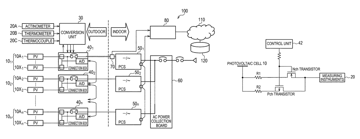
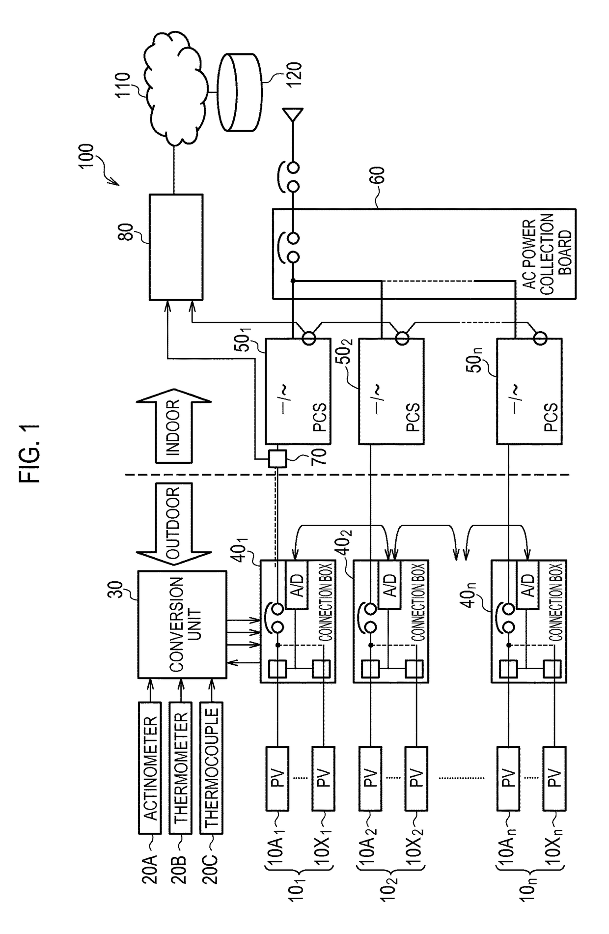
[0044]A power management system according to a first embodiment will be explained below with reference to drawings. FIG. 1 shows a power management system 100 according to the first embodiment.

[0045]As shown in FIG. 1, the power management system 100 has a plurality of photovoltaic cells 10, measuring means 20, a conversion unit 30, a plurality of connection boxes 40, a plurality of PCSs 50, an AC power collection board 60, a separation device 70, a measurement processor 80, a communication network 110, and a server 120.

[0046]The plurality of photovoltaic cells 10 (PVs in FIG. 1) include photovoltaic cell cluster 101 that belongs to a first group (photovoltaic cell 10A1 to photovoltaic cell 10X1), photovoltaic cell cluster 102 that belongs to a second group (photovoltaic cell 10A2 to photovoltaic cell 10X2), . . . , and photovoltaic cell cluster 10n that belongs to an nth group (photovoltaic cell 10An to photovoltaic cell 10Xn).

[0047]A...


PUM


Abstract

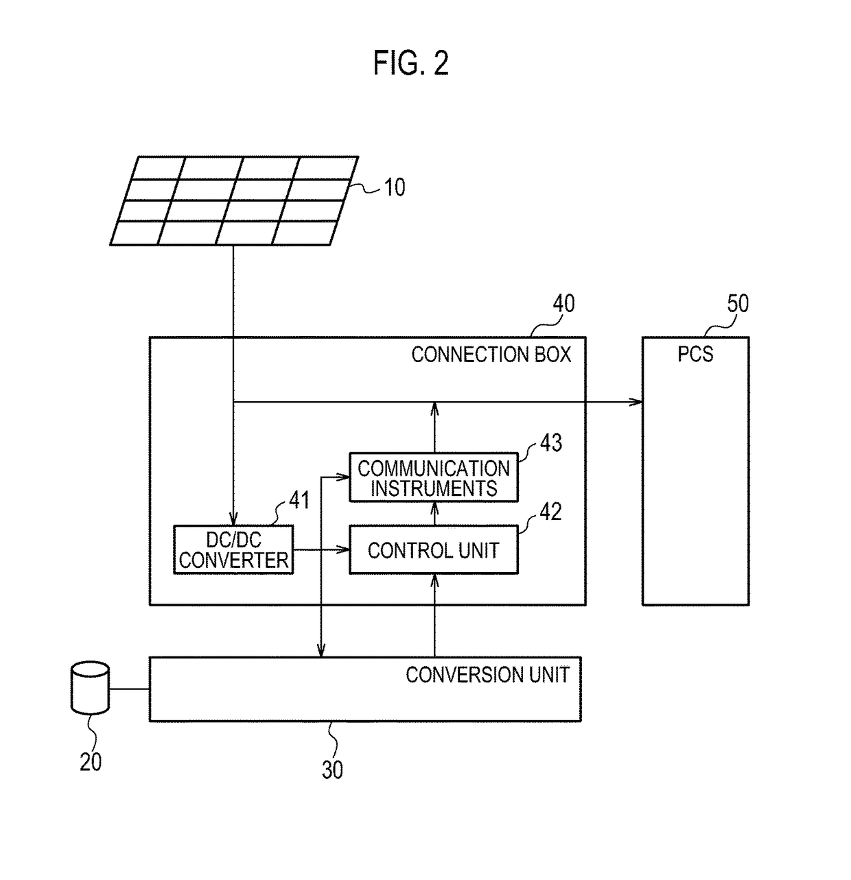
A power management system has power supplying means, measuring means that measures power generation environment for the power supplying means, and communication means that transmits information measured by the measuring means. The power management system comprises: a control unit that controls the measuring means and the communication means. The power supplying means is used as a power source for the measuring means and the communication means. The control unit sets a first power threshold to be used for determining whether or not to switch operation states of the measuring means and a second power threshold to be used for determining whether or not to switch operation states of the communication means on the basis of a power supply that is supplied from the power supplying means.

Description

TECHNICAL FIELD[0001]The present invention relates to a power management system provided with power supplying means represented by photovoltaic cells, measuring means that measures a power generation environment for the power supplying means, and communication means that transmits information measured by the measuring means, and relates also to a power management method.BACKGROUND ART[0002]A conventionally known technology is to change operation power points of photovoltaic cells so as to maximize an amount of power generated by photovoltaic cells. Such a technique is called MPPT (Maximum Power Point Tracking) method (for example, PTL 1).[0003]Also known is a system (hereinafter referred to as EMS: Energy Management System) for controlling an interconnection between photovoltaic cells and a power system. The EMS controls such that power generated by photovoltaic cells is output to the power system side (reverse power flow control), and so forth.[0004]Since the amount of power genera...

Claims


Application Information

Patent Timeline
Patent Type & Authority Patents(United States)
IPC IPC(8): H02J1/00H02J3/38H02J13/00H04Q9/00
CPCH02J1/00H02J3/383H02J13/0006H02J13/0024H02J13/0079H04Q9/00H04Q2209/823H04Q2209/886Y02E10/563Y02E40/72Y04S10/123Y10T307/344Y10T307/832H02J13/00009H02J2300/24H02J3/381H02J13/00028H02J13/00034Y02E10/56Y02E40/70Y02E60/00Y04S40/121
Inventor SASAKI, YASUSHIKUCHIKI, NOBUOBABA, TAKASHIKITAJI, MITSUHIRO
Owner KYOCERA CORP
Learn More