Forearm and wrist fracture table

a wrist and wrist technology, applied in the field of external support devices, can solve the problems of increasing the potential for infection, requiring a second surgery for the removal of the patient, and causing extensive trauma to the patien

Inactive Publication Date: 2017-09-12
RAMAZANIAN TAGHI +2
View PDF14 Cites 11 Cited by
  • Summary
  • Abstract
  • Description
  • Claims
  • Application Information

AI Technical Summary

Benefits of technology

[0011]One aspect of the present disclosure is directed to a forearm and wrist fracture table configured to support a fractured arm of a patient during a medical procedure in order to rectify a fracture site of the fractured arm, comprising a set of support base members; a set of vertical bars comprising a first vertical bar and a second vertical bar removably attached on upper surfaces of each of the support base members; a set of horizontal bars removably attached between the support base members and the vertical bars, wherein the horizontal bars are configured to provide horizontal stability and length adjustment between the support base members and the vertical bars according to the size of the fractured arm; an elbow support member defined by a cylindrical member removably attached on an upper section of the first vertical bar, wherein the elbow support member provides support for the elbow of the fractured arm; a hand support member defined by a curved plate member removably attached to an upper section of the second vertical bar, wherein the hand support member is configured to receive and support a hand extending from the elbow of the patient, wherein the fractured arm is supported between the elbow support member and the hand support member, and further wherein the support device allows for the needing pressure to be modulated and adjusted as required to distract fracture fragments, and thereby reduce and heal the fracture site.
[0025]In one embodiment, the forearm and wrist fracture table allows a surgeon to modulate an amount of needing pressure required to distract fracture fragments which reduces and heals the fracture site, and simultaneously allows the surgeon to 1) perform a cutaneous pinning technique on the fractured arm, and 2) evaluate the fractured site via x-ray when modulating the amount of needing pressure required to distract fracture fragments. This allows the surgeon to perform traction and reduction maneuvers on the fracture site, thereby reducing the fracture. In addition, the fastening wheel further comprises a handle configured to rotate the fastening wheel and fine tune the fastening wheel to adjust the fracture site.

Problems solved by technology
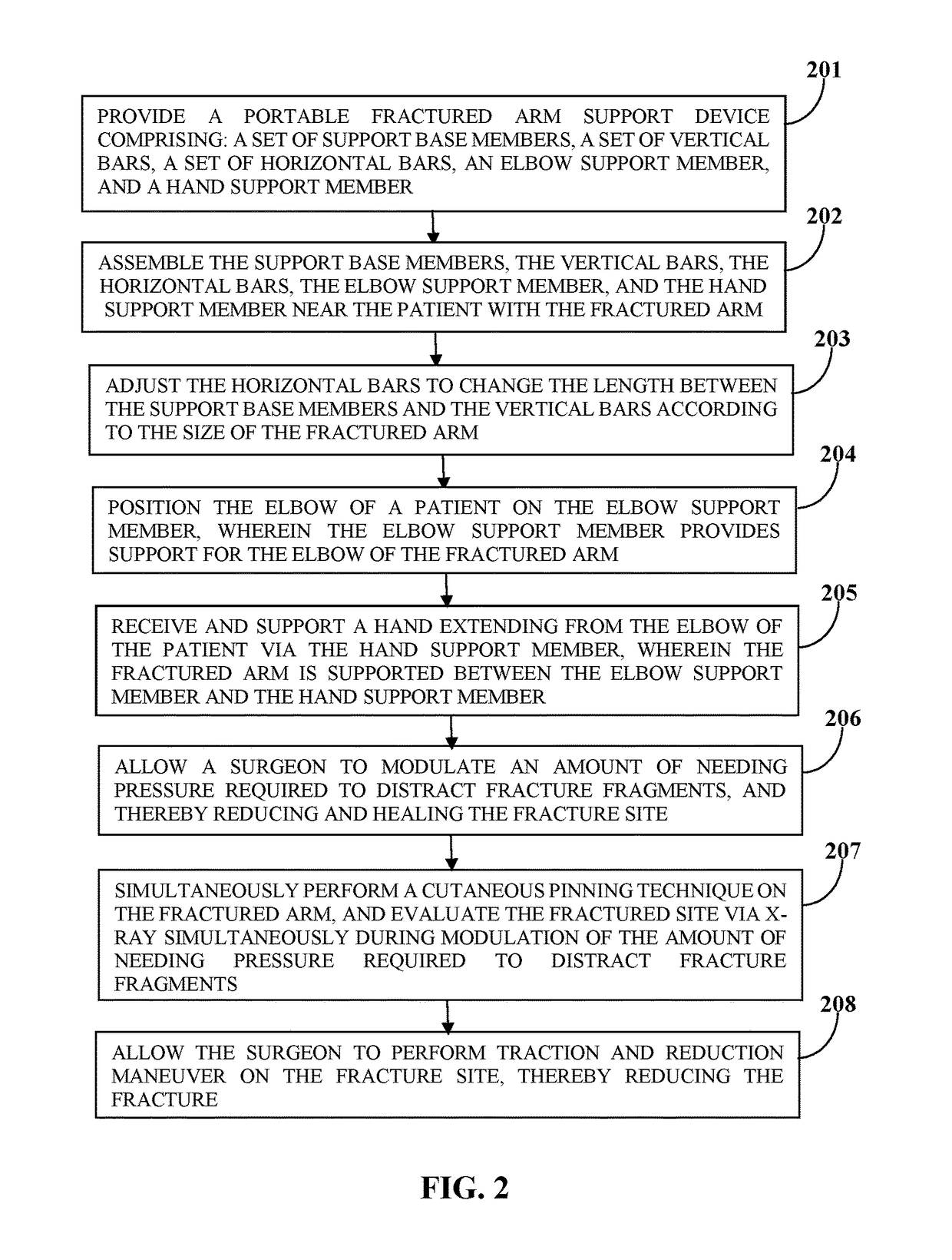
The surgical implantation of these internal fixation devices, however, may cause extensive trauma to the patient, increase potential for infection, and require second surgery for their removal.
Orthopedic surgeons generally try to reduce bone fractures in patients under general or local anesthesia to relieve pain and muscle spasm, but because of the compression or overriding of the fracture fragments, it is at times necessary to disengage the fracture fragments as a first step of the reducing process.
In situations where the fracture site is too swollen to put a cast on it; the case is not used in such situations because it would pose a great risk due to the potential for blocking of the blood supply to the forearm and hand.
After reduction of the fracture, the orthopedic surgeon orders an x-ray to evaluate fracture reduction because of the risk of displacement due to the decrease in swelling and due to the loss of the cast fitness and collapsing the fracture fragments.
In the above mentioned medical procedures, there is a lack of an adjustable device which can provide proper stabilization of the upper arm, so that the surgeon can work on the fracture fragments as well as perform x-ray on the fracture site in a steady and stable manner.

Method used


Image

  • Forearm and wrist fracture table
  • Forearm and wrist fracture table
  • Forearm and wrist fracture table

Examples


Embodiment Construction

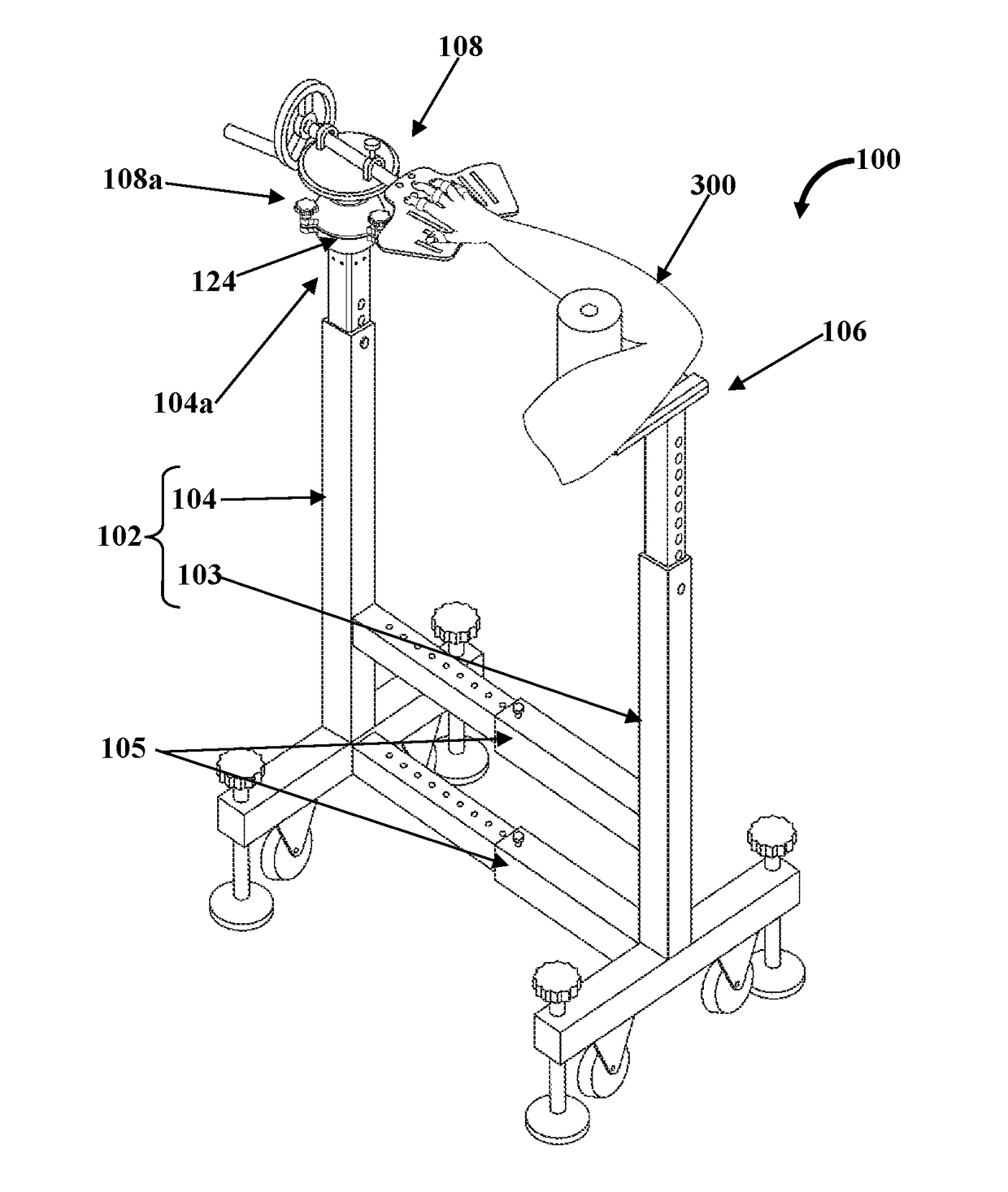
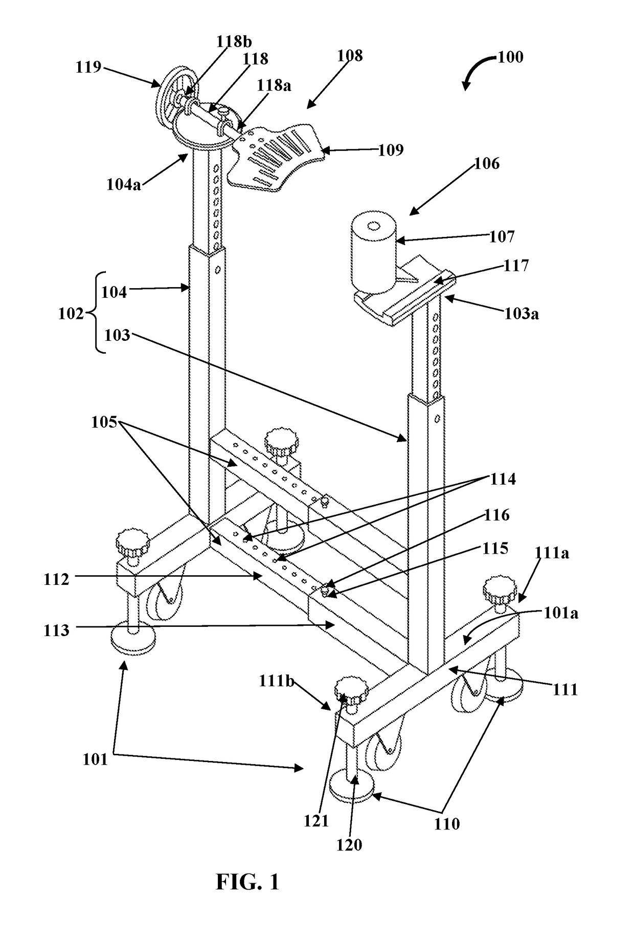
[0037]The present disclosure generally relates to the field of devices for fracture reduction and fracture repair and more specifically relates to a device for supporting a fractured arm during fracture reduction surgery and fluoroscopy imaging.

[0038]FIG. 1 exemplarily illustrates a front perspective view of a forearm and wrist fracture table 100. The forearm and wrist fracture table 100 is configured to support a fractured arm 300 of a patient during a medical procedure to rectify a fractured site of the fractured arm 300. The forearm and wrist fracture table 100 comprises a set of support base members 101, a set of vertical bars 102, a set of horizontal bars 105, an elbow support member 106, and a hand support member 108. The vertical bars 102 comprises a first vertical bar 103 and a second vertical bar 104, removably attached on upper surfaces 101a of each of the support base members 101. The horizontal bars 105 are removably attached between the support base members 101 and the ...


PUM


Abstract

A forearm and wrist fracture table includes base members, vertical bars, horizontal bars, an elbow support member and a hand support member. The vertical bars includes a first vertical bar and a second vertical bar attached to the support base members. The horizontal bars are attached between the support base members and vertical bars to provide horizontal stability and length adjustment between the support base members and the vertical bars. The elbow support member is attached to the first vertical bar to provide support for the elbow. The hand support member is attached to the second vertical bar to receive and support a hand extending from the elbow, wherein the fractured arm is supported between the elbow support member and the hand support member, wherein a surgeon is allowed to modulate an amount of needing pressure required to distract fracture fragments, and thereby reducing fracture and healing the fracture site.

Description

BACKGROUND[0001]The present invention relates to an external support device, which is designed to assist in the corrective treatment of bone fractures.[0002]Bone fractures are typically treated by restoring the fractured pieces of bone to their natural positions and maintaining those positions while the bone heals. Briefly, the fractured bone(s) is aligned in good position (also called reduction) and then immobilized with a cast that holds the bones in position and immobilizes the joints above and below the fracture. When the initial post-fracture edema or swelling goes down, the fracture may be placed in a removable brace or orthosis. In cases of complex or open fractures, surgical nails, screws, plates and wires may be used to internally hold the fractured bone together.[0003]The surgical implantation of these internal fixation devices, however, may cause extensive trauma to the patient, increase potential for infection, and require second surgery for their removal. An alternative...

Claims


Application Information

Patent Timeline
Patent Type & Authority Patents(United States)
IPC IPC(8): A61F5/042A61B17/60A61H1/02
CPCA61F5/042A61H1/0222A61H1/0285A61B17/60A61H1/0274A61H2201/0192A61H2201/1253A61H2201/1638A61G13/0045A61B6/0407A61G13/08A61G13/1235A61G13/124A61G13/129A61G13/1295A61G2210/50
Inventor RAMAZANIAN, TAGHIGHAREHBEGLOU, MOHAMMADHOODESHENAS, SAFA
Owner RAMAZANIAN TAGHI
Why Eureka
Try Eureka