
Lightning protection system

a protection system and light technology, applied in the field of lightning protection system, to achieve the effect of reducing the cos

Active Publication Date: 2017-09-19
SIEMENS GAMESA RENEWABLE ENERGY AS
View PDF10 Cites 1 Cited by
  • Summary
  • Abstract
  • Description
  • Claims
  • Application Information

AI Technical Summary

Benefits of technology

[0010]An obvious advantage of the invention is that, since the structural reinforcing elements are electrically connected to each other and to the ground terminal, any current arising during a lightning strike is diverted through the structural reinforcing elements in a controlled manner, so that an undesirable ‘side-flash’ or ‘flash-over’ through free space or concrete to a structural element is avoided, with the very favourable advantage that the structural stability of the concrete tower is protected from lightning damage. Also, since the electrically conducting structural elements are intentionally used to actively divert the current into the ground terminal, the lightning protection system according to the invention can be realized at a lower cost than a comparable lightning protection system realized externally to the tower wall. Furthermore, since the lightning protection system is incorporated in the concrete tower during construction, a time-consuming installation procedure after completion of the tower is not required.
[0011]The method according to the invention of incorporating a lightning protection system in a reinforced concrete tower comprises the steps of mounting climbing rods to a currently uppermost level of the tower and assembling a casting form to enclose the climbing rods. The method comprises the subsequent steps of placing additional electrically conductive structural reinforcing elements in the casting form, electrically connecting the structural reinforcing elements to a ground terminal and then pouring concrete into the casting form to embed the structural reinforcing elements.
[0012]According to the invention, such a lightning protection system is used in a reinforced concrete tower, preferably in a reinforced concrete tower of a wind turbine.
[0013]A wind turbine according to the invention comprises such a lightning protection system in a reinforced concrete tower of the wind turbine.
[0014]Particularly advantageous embodiments and features of the invention are given by the dependent claims, as revealed in the following description.
[0015]Tower structures can be constructed on-site for various different situations. For example, concrete piers for bridges may be cast on site. Concrete pylons may be constructed for carrying cable cars, etc. For various reasons, a tall tower structure such as a television tower or a wind turbine tower is usually hollow. For one, such a structure is stable. Furthermore, many types of tall towers require some mode of access to the equipment mounted on top of the tower. In the following, without restricting the invention in any way, a hollow tower is assumed, although the inventive lightning protection system could also equally well be used for a solid tower structure.

Problems solved by technology

Furthermore, since the lightning protection system is incorporated in the concrete tower during construction, a time-consuming installation procedure after completion of the tower is not required.

Method used


Image

  • Lightning protection system
  • Lightning protection system
  • Lightning protection system

Examples


Embodiment Construction

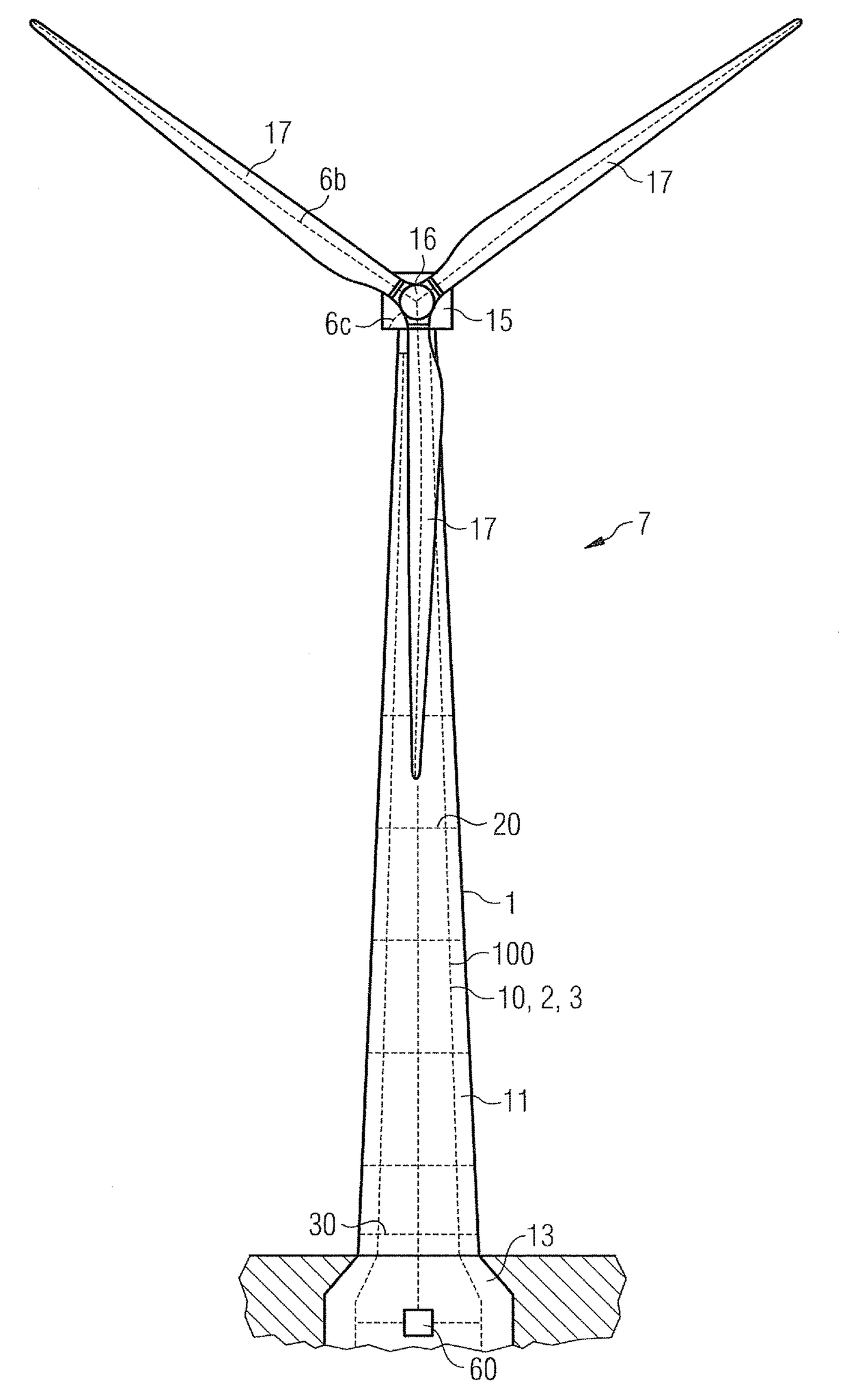
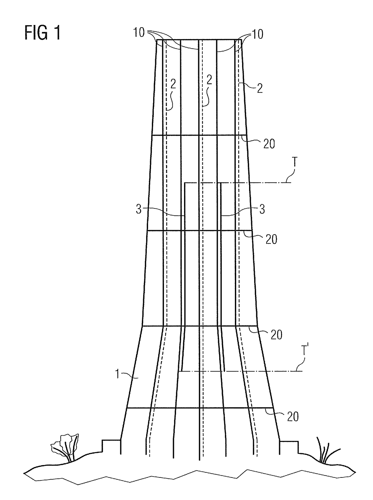
[0039]FIG. 1 shows a very simplified schematic representation of a lightning protection system 100 according to the invention incorporated in a hollow concrete tower 1. The solid lines indicate earthing cables 10 incorporated in the concrete tower wall 11. The dotted lines indicate climbing rods 2, and the shorter solid lines in the region T-T′ indicate post-tensioning cables 3 or tendons 3. Typically, a tall tower structure 1 has a short lower region with a more pronounced conical shape, and a long upper region which tapers more gradually. In this embodiment, the tendons 3 are incorporated over a part of the tower height. At their base, the tendons are anchored in the tower wall. At their top, the tendons 3 are hydraulically tightened to preload the concrete tower wall. The diagram also shows a number of horizontal lightning protection rings 20 at various levels, which ensure that electrical equipotentials are achieved at all these levels. In practice, for a tower 1 with a height o...


PUM


Abstract

A lightning protection system for a tower of a wind turbine is provided. The tower includes a reinforced concrete tower wall in which a plurality of electrically conductive structural reinforcing elements are embedded during construction. The lightning protection system includes a plurality of the structural reinforcing elements connected in an electrically conductive manner with each other and with a ground terminal. Further, a method of incorporating such a lightning protection system in a reinforced concrete tower, and a wind turbine with such a lightning protection system is provided.

Description

CROSS REFERENCE TO RELATED APPLICATIONS[0001]This application is the U.S. National Stage of International Application No. PCT / EP2010 / 050472 filed Jan. 15, 2010, and claims the benefit thereof. The International Application claims the benefits of U.S. Provisional Application No. 61 / 236,192 US filed Aug. 24, 2009. All of the applications are incorporated by reference herein in their entirety.FIELD OF INVENTION[0002]The invention describes a lightning protection system for a tower constructed in-situ in one piece.BACKGROUND OF INVENTION[0003]For any tall construction exposed to the elements, lightning protection is an important aspect. A tall construction must incorporate some way of conducting the electrical current to ground in the event of a lightning strike. In its simplest form, a lightning protection system (LPS) can comprise a lightning rod which is generally higher than the building to which it is attached, and which is connected to a metal strip or other electrical conductor l...

Claims


Application Information

Patent Timeline
Patent Type & Authority Patents(United States)
IPC IPC(8): E04H12/12F03D13/20F03D80/30H02G13/00
CPCH02G13/00E04H12/12F03D13/20F03D80/30H02G13/40Y02E10/728Y02E10/72F03D13/10F03D13/22
Inventor JENSEN, MARTIN JOHAN SMITHLEWKE, BASTIANOLSEN, KAJ
Owner SIEMENS GAMESA RENEWABLE ENERGY AS
Learn More