Method for profiling a replacement blade as a replacement part for an old blade for an axial-flow turbomachine

a technology of axial flow turbomachine and replacement blade, which is applied in the direction of blade accessories, machines/engines, stators, etc., can solve the problems of affecting the efficiency of the stage, affecting the positive influence of the rearward sweep on stage efficiency, and affecting the aerodynamic influence of the transition sweep. , the effect of reducing the structural disadvantage of the blade provided

Active Publication Date: 2017-09-26
SIEMENS ENERGY GLOBAL GMBH & CO KG
View PDF24 Cites 4 Cited by
  • Summary
  • Abstract
  • Description
  • Claims
  • Application Information

AI Technical Summary

Benefits of technology

[0010]An object herein is to provide a method for profiling a replacement blade as a replacement part for an old blade for an axial-flow turbomachine, a rotor blade and a stator blade for a gas turbine and also the gas turbine with the rotor blade and / or with the stator blade, the gas turbine having high thermodynamic efficiency.
[0018]In this case, the old blade is demounted, for example, from a rotor of the gas turbine and the replacement blade is mounted in place of the old blade. The old blade or replacement blade is usually tension-mounted with a form fit on the rotor of the gas turbine. Since the center of gravity of the replacement blade lies essentially in the same axial position as the center of gravity of the old blade and / or the mechanical integrity of the replacement blade is achieved, utilizing the maximum utilizable axial construction space of the old blade, the stress upon the form-fit fastening of the replacement blade is essentially equal to the load upon the form-fit fastening of the old blade. This is advantageous particularly because, by the rearward sweep being provided in the profiling of the replacement blade, to achieve high stage efficiency the mechanical load upon the blade fastening when the gas turbine is in operation with the replacement blade is essentially equal to that arising when the gas turbine is in operation with the old blade.
[0019]The transition sweep is restricted locally to the region which is near the tension mounting and which impairs the positive influence of the rearward sweep upon stage efficiency to only a slight extent. As a result, the aerodynamic influence of the transition sweep is low, whereas structural disadvantages of a blade provided as standard with a rearward sweep are reduced. The transition sweep is preferably limited to a region of 5% to 15% of the blade height of the replacement blade. The benefit of the rearward sweep can thus be utilized in the range of higher flow velocities outside 5% to 15% of the blade height of the replacement blade. Moreover, in the rotor blade according to aspects of the invention, the distance from a downstream conventional stator blade is greater than if a rotor blade were provided in the customary way with the rearward sweep and without the transition sweep. Consequently, excitation caused by aerodynamic forces brought about by the rotation of the rotor blade according to aspects of the invention is slight.

Problems solved by technology

If, however, the profiling of the new blading leads to a change in the centers of gravity of the airfoils, the mechanical stress upon the blade fastening changes.
As a rule, this leads to adverse loads upon the blade fastening, therefore the profiling of the new blading has to be coordinated with the maximum permissible load values of the blade fastening.
As a rule, this results in restrictions in the profiling of the new blading, the result of this being that efficiency increases which can be achieved in principle cannot be implemented.
Owing to this displacement of centers of gravity, the recently prevailing symmetry of the load upon the blade fastening within the blade grooves is impaired, so that the degree of rearward sweep is severely limited in the profile of the compressor rotor blades.
On account of this, however, an appreciable potential and efficiency improvement remained unused.
However, this measure would be disadvantageous in terms of the aerodynamic load bearing capacity and stability of the new blading and its structural integrity.

Method used


Image

  • Method for profiling a replacement blade as a replacement part for an old blade for an axial-flow turbomachine
  • Method for profiling a replacement blade as a replacement part for an old blade for an axial-flow turbomachine
  • Method for profiling a replacement blade as a replacement part for an old blade for an axial-flow turbomachine

Examples


Embodiment Construction

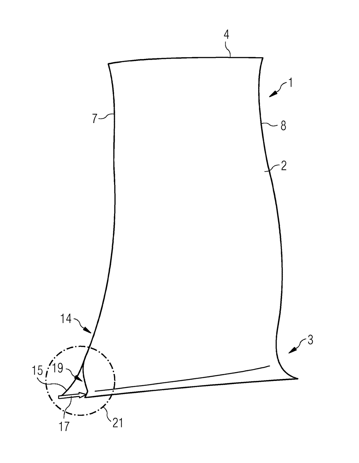
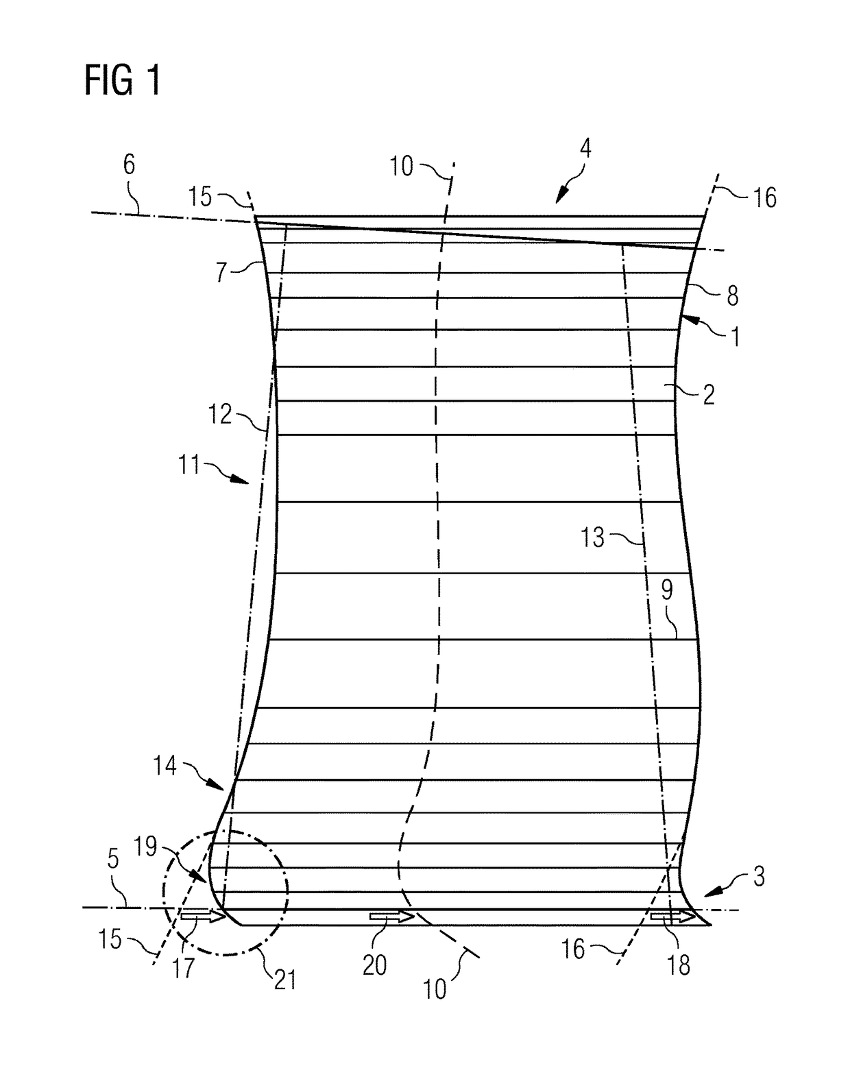
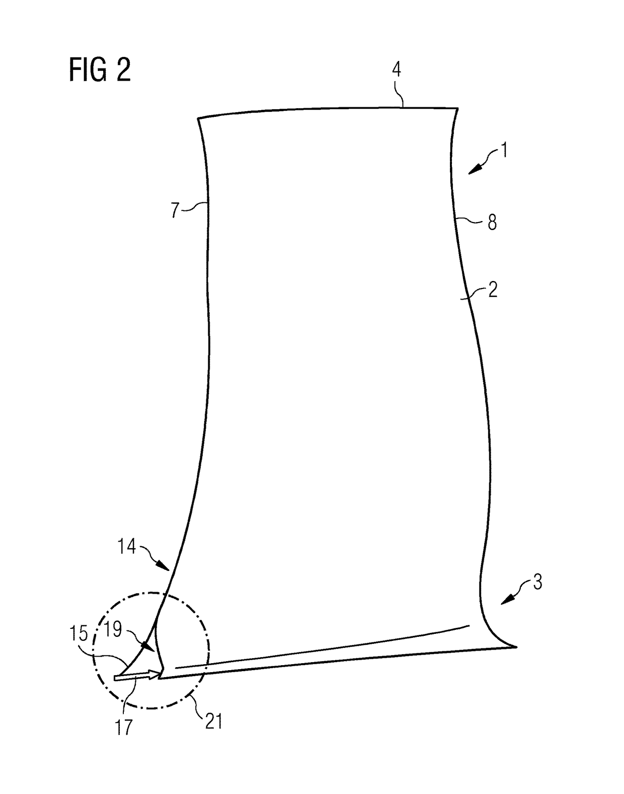
[0023]As is evident from FIGS. 1 and 2, a replacement blade 1 which is a rotor blade has an airfoil 2 and a blade root 3 which can be tension-mounted at a blade foot (not shown) with a rotor of a gas turbine by means of a form fit. For this purpose, the blade foot, which has a foot profile, is formed at the blade root 3. As a counterpiece to this, a groove with a corresponding profile is provided in the rotor, the blade foot being insertable into the groove.

[0024]At the radially facing-away end of the blade 2, the replacement blade 1 has a blade tip 4. When the replacement blade 1 is in the installed state, the blade tip 4 is arranged directly adjacently to a casing inside, a radial gap thereby being formed between the casing inside and the blade tip 4. In the design state, the blade tip 4 coincides with a casing contour line 6 which, as a consequence of operation, is stipulated for the installation and operation of the replacement blade 1 in the gas turbine. In a similar way to thi...


PUM

PropertyMeasurementUnit
gravityaaaaaaaaaa
distanceaaaaaaaaaa
heightaaaaaaaaaa

Abstract

A method for profiling a replacement blade for an axial turbomachine is provided. The method includes: measuring hub contour geometry and housing contour geometry of the flow channel of the old blade and the axial position of the centre of gravity of the blade aerofoil of the old blade; laying out geometry of the blade aerofoil of the replacement blade, the blade aerofoil having a rearward sweep on its leading edge; defining a region of the blade aerofoil near the mounting and in which positive influence of the rearward sweep on the degree of stage efficiency is rated as low; and axially displacing the replacement blade aerofoil section arranged outside this region in the upstream direction, until the axial position of the centre of gravity of the blade aerofoil of the replacement blade coincides with the old blade. In the region from the mounting-side section to the displaced blade aerofoil section of the replacement blade, the leading edge is inclined downstream towards the mounting such that the blade aerofoil has a transition sweep in this region.

Description

CROSS REFERENCE TO RELATED APPLICATIONS[0001]This application is the US National Stage of International Application No. PCT / EP2012 / 065842 filed Aug. 14, 2012, and claims the benefit thereof. The International Application claims the benefit of European Application No. EP11180679 filed Sep. 9, 2011 . All of the applications are incorporated by reference herein in their entirety.FIELD OF INVENTION[0002]The invention relates to a method for profiling a replacement blade as a replacement part for an old blade for an axial-flow turbomachine, the replacement blade being a rotor blade or a stator blade for a gas turbine.BACKGROUND OF INVENTION[0003]A gas turbine, in particular a non-stationary gas turbine, usually has an operating life of about 30 years. During this period of time, technical innovations, particularly for improving the thermal efficiency of the gas turbine, have hitherto become commercially viable. It is desirable that an already installed gas turbine is equipped at least pa...

Claims


Application Information

Patent Timeline
Patent Type & Authority Patents(United States)
IPC IPC(8): F01D5/14F01D5/12B23P6/00F01D9/02
CPCF01D5/12B23P6/005F01D5/141F01D5/147F01D9/02F05D2230/80Y10T29/4932
Inventor CORNELIUS, CHRISTIANMATTHIAS, TORSTEN
Owner SIEMENS ENERGY GLOBAL GMBH & CO KG
Why Eureka
Try Eureka