
Method for improving wall heat transfer in a chemical reactor

a technology of chemical reactors and walls, applied in the direction of physical/chemical process catalysts, lighting and heating equipment, soldering equipment, etc., can solve the problems of not being able to enjoy the improvement of effective thermal conductivity, too big or rigid typical packed particles or extrudates to access the surface of micro-organisms, etc., to improve the efficiency of heat transfer process, and increase the effect of heat transfer area

Active Publication Date: 2017-09-26
INSTREETCARICRON
View PDF13 Cites 0 Cited by
  • Summary
  • Abstract
  • Description
  • Claims
  • Application Information

AI Technical Summary

Benefits of technology

[0011]Methods for improving heat transfer at the interface between an internal reactor wall and mesh media containing microfibrous entrapped catalysts (MFECs) and / or microfibrous entrapped sorbents (MFESs) are described herein. Improved (e.g., more rapid) heat transfer can be achieved using a variety of approaches including (1) roughening the contacting surface of the interface between the mesh media and the reactor wall, (2) enhancing the contacting efficiency at the contacting points between the mesh media and the reactor wall, (3) increasing the number of contact points between the mesh media and the reactor wall using fine fibers, and combinations thereof. These approaches address both the heat transfer area (A) and the effective thermal conductivity (k).
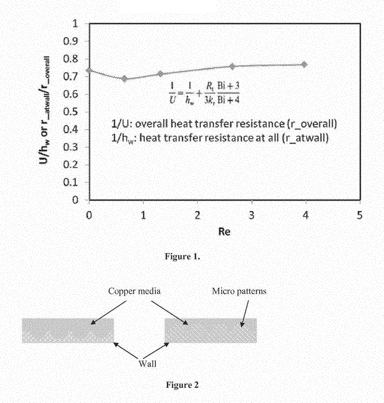
[0012]As mentioned above, increasing contact area will improve heat transfer at the wall, using a method such as roughening the internal wall surface. In the proposed approach, micro-patterns such as grooves, channels, humps, fins and sintered fibers can be made on the inner heat transfer surfaces. This allows the heat transfer area (A) to be increased significantly. Moreover, microfibrous media and MFEC are very flexible and malleable and can be deformed to match the rough surface, which can be generated by micro-patterning. As a result, more contacting point can be formed and provide improve effective thermal conductivity (k). Typical packed particles or extrudates are too big or too rigid to access the surface of micro-patterns. Therefore they cannot enjoy the improvement in effective thermal conductivity.
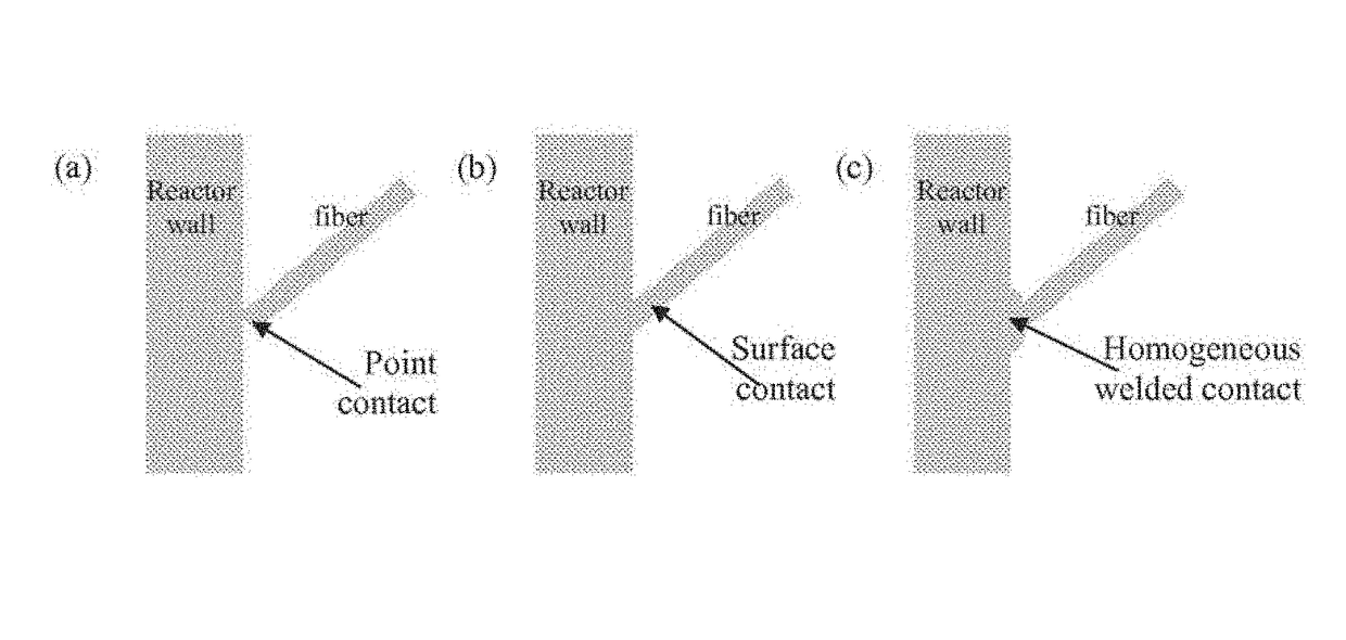
[0013]The second approach focuses on improving contact efficiency and minimizing interfacial heat transfer resistances. Ideally the inner wall and fibrous media are made of the same material (e.g. copper) and they form a single phase (i.e. continuous copper phase) without interfaces. This will certainly improve the thermal conductivity. From a different point of view, the fibers can be treated as the extension of the wall surface (increasing in heat transfer area A) when this continuous phase is formed. This ideal case can be realized by “welding” fibers on the heat transfer surface made of the same materials (FIG. 4C). In a less ideal case, fibers can be compressed, abraded and deformed on the heat transfer surface due to the tight packing during microfibrous media or MFEC loading (FIG. 4B). The wall and fibers are still two different phases. But the contacting resistance is much lower than that of a point contacts due to lose packing (FIG. 4A).
[0014]The third approach is using fine fibers to generate more contacting points and larger heat transfer area. If the fiber length and fiber volume are fixed, the smaller-diameter fibers will have much higher fiber counts than large-diameter fibers. For example, the fiber counts of 6 micron fibers will be 1 / 16 of that of 24 micron fibers. Replacing 10% of 24 micron fibers with 6 micron, will more than double the contact point count, and available fiber surface area increases by 30%. Moreover, small fibers are more flexible and can more-easily access more surface area generated by micro patterns. According to the discussion presented in the first and second approaches, the use of small fibers will certainly enhance the heat transfer area (A) and thermal conductivity (k).

Problems solved by technology

Typical packed particles or extrudates are too big or too rigid to access the surface of micro-patterns.
Therefore they cannot enjoy the improvement in effective thermal conductivity.

Method used


Image

  • Method for improving wall heat transfer in a chemical reactor
  • Method for improving wall heat transfer in a chemical reactor
  • Method for improving wall heat transfer in a chemical reactor

Examples


example 1

Fine Structural Patterns to Increase Heat Transfer on the Reactor Wall

[0030]As shown in FIG. 1, the heat transfer area on the inner reactor wall can be increased by cutting groove patterns on the surface and creating small bumps on the inner surface using solder chemicals. Because the microfibrous media are very flexible, they can be deformed to match the roughened the surface of the wall. The heat transfer area is increased by these fine structures.

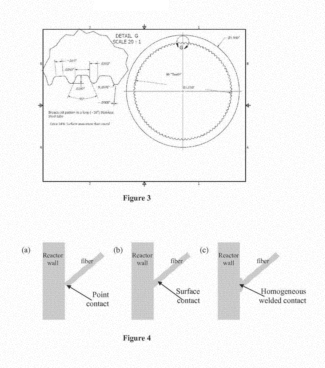
[0031]In practice, the edges of the fine structures are generally smoothed. The groove pattern in actual use is shown in FIG. 2. Heat transfer area was increased by about 34%.

example 2

Improving Contact Efficiency at Reactor Wall

[0032]Various contacting styles between the fibers and the reactor wall are shown in FIG. 3. The contact point is formed when the media is not compressed on the reactor wall. There is very limited area to conduct the heat due to the nature of the contact point. The second contact, surface contact, is generated by deforming the surface of copper fibers when a slightly larger diameter microfibrous media is inserted into the reactor tube. This media has a much larger area for heat transfer. The third contact, homogeneous welded contact, is generated by welding the fibers and the reactor wall together, which is typically carried out using solder chemicals. It should generate the largest heat transfer area among these three contacting styles. Moreover, it is the welding contact that creates homogeneous contacting and enables the lower heat transfer resistance.


PUM

PropertyMeasurementUnit
diameteraaaaaaaaaa
lengthaaaaaaaaaa
diameteraaaaaaaaaa

Abstract

Methods for improving heat transfer at the interface between the internal reactor wall and mesh media containing microfibrous entrapped catalysts (MFECs) and / or microfibrous entrapped sorbents (MFESs) are described herein. Improved (e.g., more rapid) heat transfer can be achieved using a variety of approaches including increasing the contacting area of the interface between the mesh media and the reactor wall so that more contacting points are formed, enhancing the contacting efficiency at the contacting points between the mesh media and the reactor wall, increasing the number of contact points between the mesh media and the reactor wall using fine fibers, and combinations thereof.

Description

CROSS-REFERENCE TO RELATED APPLICATIONS[0001]This application is a 371 application of International Application No. PCT / US2013 / 030837, filed Mar. 13, 2013, which claims benefit of U.S. Provisional Application Nos. 61 / 669,918, filed Jul. 10, 2012.STATEMENT REGARDING FEDERALLY SPONSORED RESEARCH OR DEVELOPMENT[0002]This invention was made with government support under Grant No. ARMY-W56HZV-05-C0686 awarded by the U.S. Army. The government has certain rights in the invention.FIELD OF THE INVENTION[0003]This invention is generally in the field of heterogeneous catalysis, particularly structural catalysts.BACKGROUND OF THE INVENTION[0004]Microfibrous entrapped catalysts (MFECs) have been developed for strong exothermic or endothermic processes. The sintered metal microfibrous structure can collect the heat from the catalyst particles, where the reaction heat is generated and transfer it to the internal reactor wall-MFEC contacting interface. MFECs made of copper microfibers demonstrate 5...

Claims


Application Information

Patent Timeline
Patent Type & Authority Patents(United States)
IPC IPC(8): F28F13/18B01J19/24B01J19/32F28F1/40B23K1/00B23K31/02B01J35/06F28D21/00F28F13/00
CPCF28F13/185B01J19/2495B01J19/32B23K1/0012B23K31/02F28F1/405F28F13/00B01J35/06F28D2021/0022F28F2013/001F28F2013/005Y10T29/49352
Inventor YANG, HONGYUNDIMICK, PAUL S.TATARCHUK, BRUCE J.
Owner INSTREETCARICRON
Learn More