Spectroscopic device

a spectroscopic device and spectroscopic technology, applied in the field of spectroscopic devices, can solve the problems of limited practicability, difficult to distinguish spectral properties, and large numerical apertures, and achieve the effects of maximizing the selectivity of wavelengths, improving performance, and spectral uniformity

Active Publication Date: 2017-09-26
GENESIA CORP
View PDF13 Cites 0 Cited by
  • Summary
  • Abstract
  • Description
  • Claims
  • Application Information

AI Technical Summary

Benefits of technology

[0011](1) The wavelength of the light that passes through an LCTF depends on the angle of incidence of the light aiming to the LCTF. This effect produces the field-position-dependence of the central wavelength of the transmitting band, and leads spectral ununiformity of the image, which is depending on the location of the optical sensor in the optical unit as a spectrograph, or leads broadening of the transmitted bandwidth. These disadvantages are particularly significant with a wide field camera, and / or with larger numerical aperture.
[0020]Therefore, when the optical tunable filter (that is used as a bandpass filter which can vary the wavelength where it is at the peak transmittance) is disposed in the space where the optical tunable filter is installed or disposed, at least one ray in a beam propagating from each of object point always being incident normal to the optical tunable filter, even if the field of view is wide and / or numerical aperture of the optical unit is large. In particular, when the oblique angle of the chief ray is zero (parallel to the optical axis), the oblique angles of corresponding marginal rays in the beam are minimized, so that the angles of incidence for any rays in the corresponding beam are also minimized to the normal to the optical tunable filter, which can maximize the selectivity of the wavelength by the optical unit.
[0021]For the design of optical unit as stated above, it is desirable that the clear aperture of beams passing through the optical tunable filter are larger than the entrance pupil diameter of the optical unit, because this condition can leads making oblique angle of the rays onto the optical tunable filter (or the oblique angle with respect to the optical axis) smaller, and causes better performances to obtain both spectral uniformity and minimum broadening in bandwidth. In this way, a whole detected image can be tuned into the interesting unique wavelength band, uniformly and can be reduced the broadening of the bandwidth, even for a wide field of view and / or a large numerical aperture.
[0022]Also, by installing a depolarizer in front of the optical tunable filter in the optical unit of the present invention, the spectral properties of the object being measured itself can be extracted without being affected by polarized light, even when the light beams from the object being measured includes polarized light components. Also, by disposing a polarizer in front of the depolarizer, the polarized light component from a specific direction only can be extracted. In addition, by providing a mechanical and / or electronical rotator capable of controlling the light polarization direction as desired, the phase conversion of the polarized light can be easily adjusted, so any of the complex amplitude information (wavelength information, amplitude information, and phase information) included in the light from the object can be easily acquired.

Problems solved by technology

However, LCTFs have the following two technical weaknesses, which have limited their practicability.
These disadvantages are particularly significant with a wide field camera, and / or with larger numerical aperture.
Therefore, it is difficult to distinguish the spectral properties from the polarization state which is deeply relating to the observing conditions of the objects.

Method used


Image

  • Spectroscopic device
  • Spectroscopic device
  • Spectroscopic device

Examples


Embodiment Construction

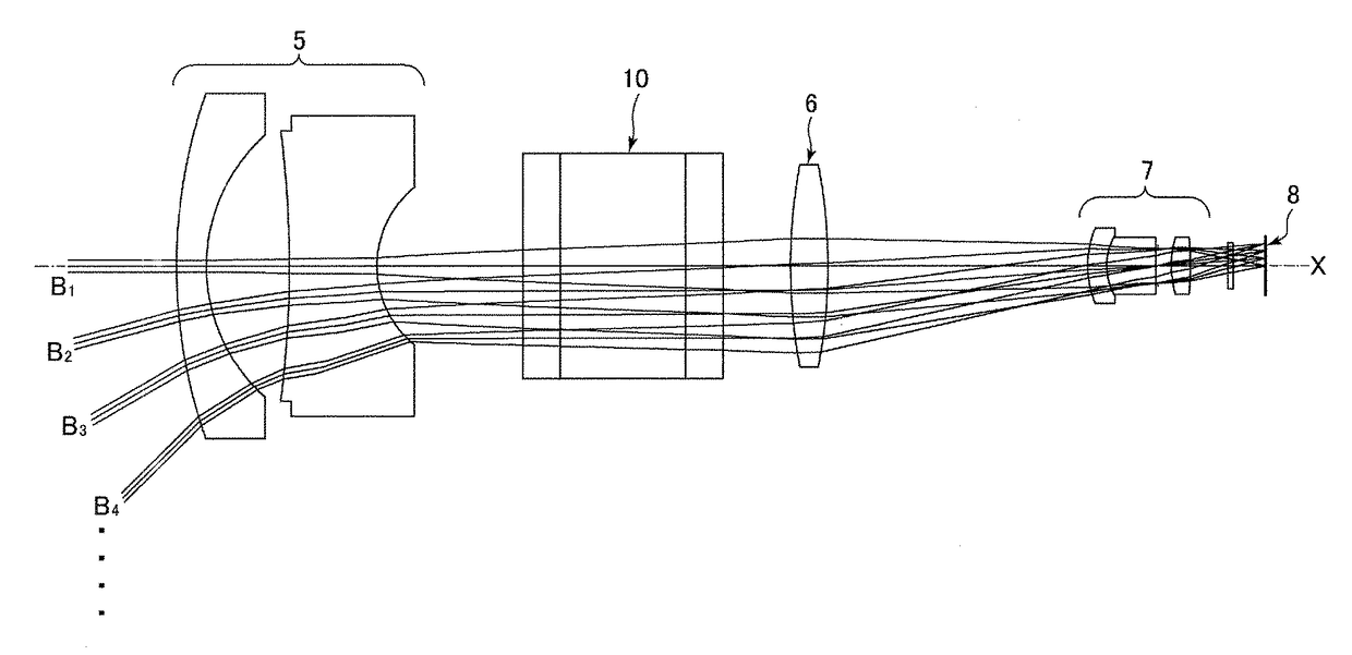
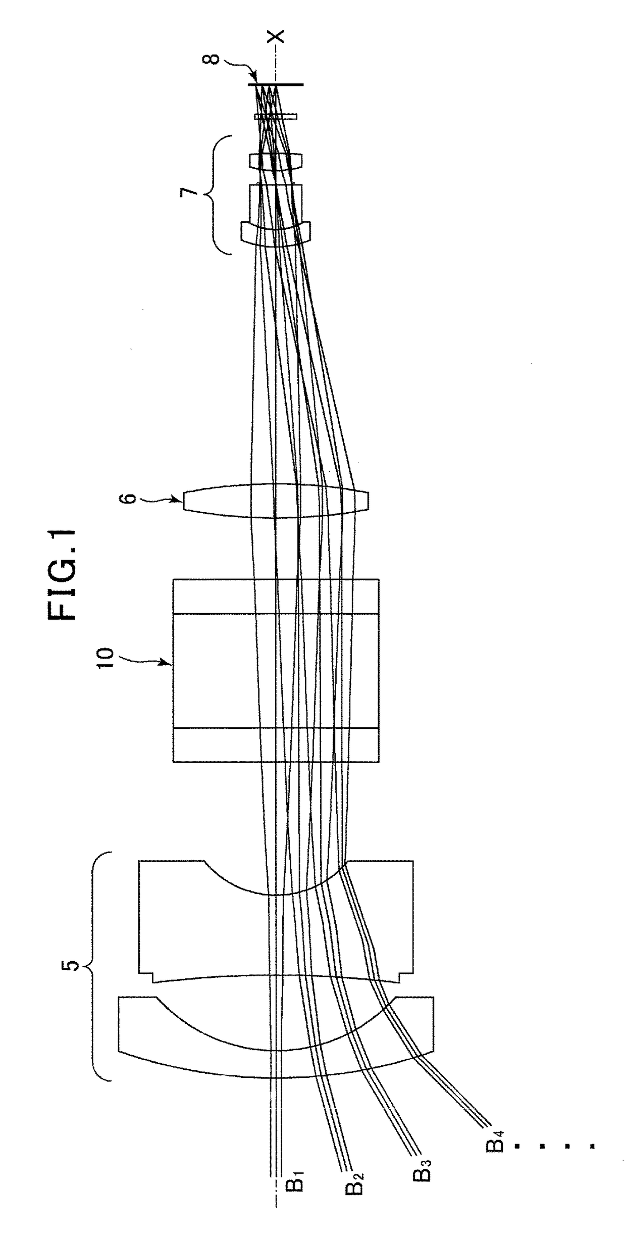
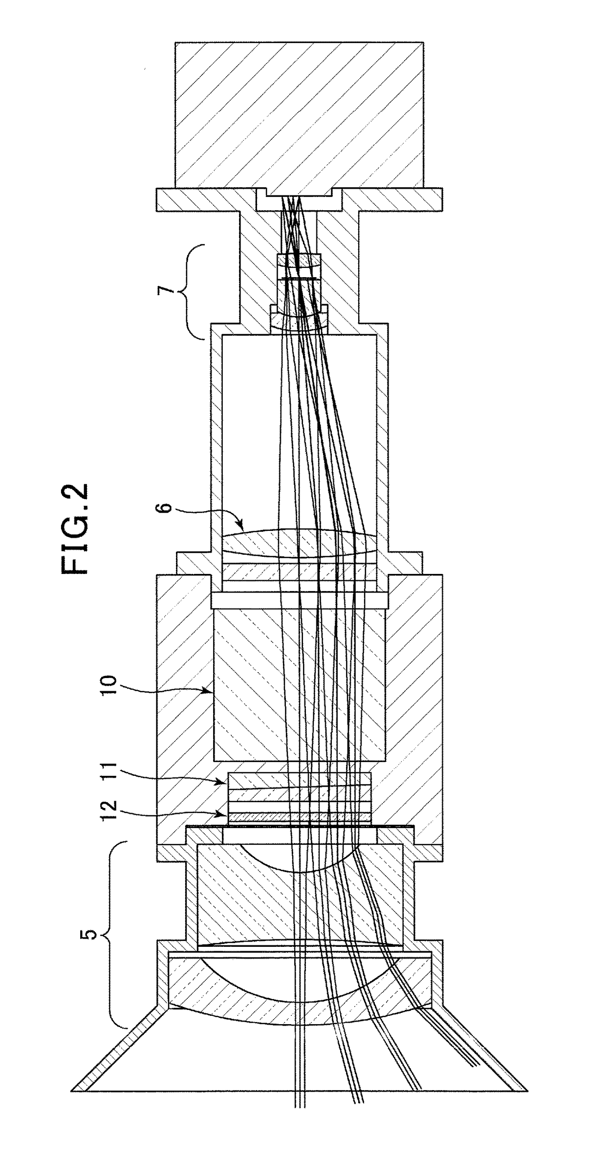
[0032]The following is a description of an embodiment of the optical lens according to the present invention, with reference to the drawings. Note that a variable central wavelength filter disposed in the optical lens of the present invention is described as a liquid crystal tunable filter (hereinafter, referred to as an “LCTF”), but it is not limited, and can be installed any other types of variable central wavelength filter, such as a tunable Fabry-Perot interferometer.

[0033]To clarify the differences between the present invention and the conventional technology, a conventional spectroscopic device using an LCTF will be described first. As illustrated in FIG. 5, an LCTF 10 is configured from a plurality of units stacked to form a laminate-based configuration, and the each unit of the plurality of units comprises a liquid crystal cell 1, a birefringence filter 2, and a polarizing element (polarizing filter) 3. In other words, the LCTF 10 includes a multiple of stages configured fro...


PUM

PropertyMeasurementUnit
wavelengthsaaaaaaaaaa
incident angleaaaaaaaaaa
wavelength bandaaaaaaaaaa

Abstract

A spectroscope device is provided to maintain the uniformity of the central transmitting wavelength in the field of view and to minimize the broaden of the bandwidth of the transmitting wavelengths in an optical lens using an optical tunable filter (variable wavelength filter), even with a wide field of view and / or a large numerical aperture. A space is defined in which, when each beam that is incident from each off-axial object point on the object surface toward the optical lens that includes a plurality of lens elements between an object surface and a conjugate real image surface reaches the optical tunable filter, the chief ray is maintained parallel to the optical axis. Therefore, if an optical tunable filter is disposed in this space, each beam is always incident normal to the filter, so only the narrow band components at the specific central wavelength can be transmitted.

Description

FIELD OF THE INVENTION[0001]The present invention relates to technology for acquiring and analyzing spectrographic properties that reflect at least one of the physical, chemical, and biological states of an object being measured, and in particular relates to technology for the structure of an optical lens in a spectroscopic device for determining the type and / or state of an object being measured using an optical tunable filter (wavelength-tunable filter).DESCRIPTION OF THE RELATED ART[0002]A 3-dimensional image obtained by associating spectrographic wavelength information (X coordinate) with to the 2-dimensional positional information (X and Y coordinates) of an object being measured is referred to as a hyperspectral image, and be corresponds to a series sets of data consisted of images for many narrow bands of wavelength. The simplest hyperspectral image is the so-called color image (true color image) that is expressed by the intensity ratios of three color elements, for example re...

Claims


Application Information

Patent Timeline
Patent Type & Authority Patents(United States)
IPC IPC(8): G01J3/00G01J3/28G02F1/1335G01J3/02G02B13/16
CPCG01J3/0208G01J3/2823G02B13/16G02F1/133528G01J3/12G01J3/32G01J2003/1247G01J2003/1269G01J3/0224
Inventor TAKEYAMA, NORIHIDEKANAI, YOSHIKAZUFUKUOKA, DAISUKE
Owner GENESIA CORP
Why Eureka
Try Eureka