
Artificial eye with an internal electromagnetic drive

a technology of electromagnetic drive and artificial eye, which is applied in the field of artificial eye simulating human or humanlike eyes, can solve the problems of increased manufacturing complexity and cost, unsatisfactory visible in some applications, etc., and achieve the effects of reducing complexity, reducing space, and small form factor

Active Publication Date: 2017-10-03
DISNEY ENTERPRISES INC
View PDF24 Cites 6 Cited by
  • Summary
  • Abstract
  • Description
  • Claims
  • Application Information

AI Technical Summary

Benefits of technology

The solution provides a more realistic and compact eye movement simulation with reduced maintenance needs, hiding drive components for a wider range of applications and reducing manufacturing complexity, while offering low power consumption and increased angular range of motion.

Problems solved by technology

While the flotation-based animatronic eye described in the background is relatively compact and is useful for providing frictionless yaw and pitch movements simulating eye movements, the inventors identified several operational issues or challenges with its use.
This animatronic eye makes use of external coils in its electromagnetic drive (i.e., used an “external electromagnetic drive” with the drive coils outside the outer shell and the permanent magnets at the surface of the inner sphere or eye), and these coils extended outward, which made them undesirably visible in some applications such as for characters where a large portion of the eye is uncovered (e.g., for an animatronic lizard).
As mentioned above, the coils were then visible in many applications, which often is undesirable as it is desirable to hide the drive components to give the illusion of a natural eye.
Additionally, the four magnets provided on the surface of the inner eye or sphere use a small permanent magnet centered between each coil pair on the outer surface of the outer shell as a return spring for the inner eye sphere (return to center when drive forces are removed), and this increased manufacturing complexity and costs.

Method used


Image

  • Artificial eye with an internal electromagnetic drive
  • Artificial eye with an internal electromagnetic drive
  • Artificial eye with an internal electromagnetic drive

Examples


Embodiment Construction

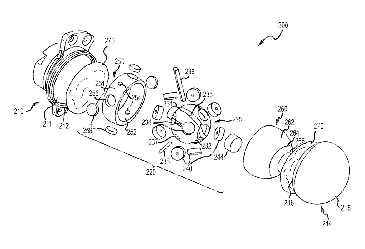
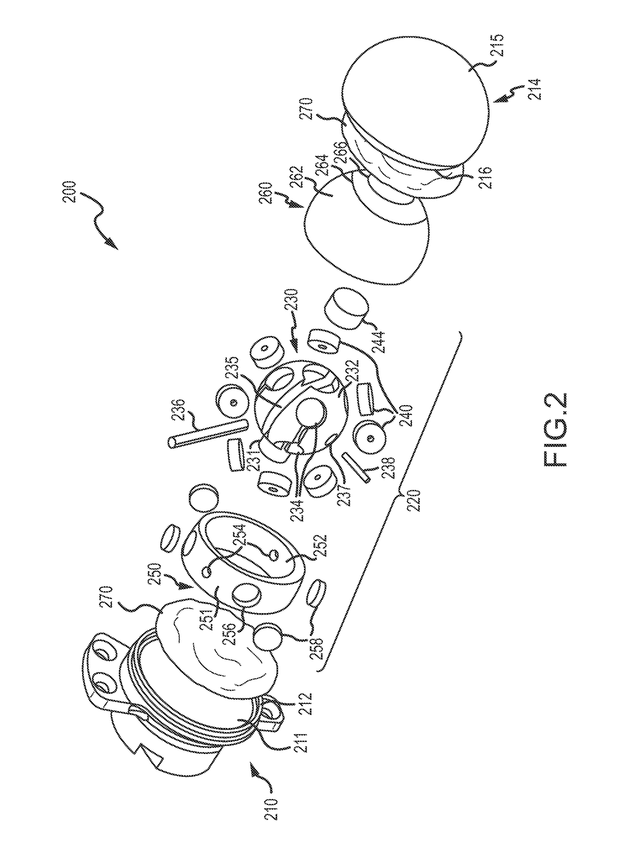
[0024]Briefly, embodiments described herein are directed to a compact, fluid-covered (not suspended), electromagnetically-gimbaled (or driven) eye that may be used in eye assemblies for animatronic figures as well as for human prosthetics. Each eye or eye assembly features extremely low operating power, a range of motion and saccade speeds that may exceed that of the human eye while providing an absence of frictional wear points (e.g., between the eyeball or inner sphere and an eye socket). The design of the eye assembly has no external moving parts, which eases its installation in new and retrofit animatronic applications.

[0025]The eye assembly (or artificial eye or animatronic / robotic eye) described herein uses a centrally positioned, omnidirectional, pivoting bearing (or pivotal joint or mount) to support the inner eye or sphere. The bearing or pivotal joint can be attached to a post or base member, which, in turn, can be affixed to the outer shell (e.g., the inner half of the ou...


PUM


Abstract

An artificial eye for use with an animatronic figure or a robot. The artificial eye includes an outer shell formed with a wall defining a spherical inner void space. The outer shell includes a transparent outer or forward portion or half joined with a rear portion or half. The artificial eye includes an inner eye or sphere including a hollow, semi-spherical shell, and the inner eye is positioned in the inner void space of the outer shell. The artificial eye includes an electromagnetic drive positioned within the hollow, semi-spherical shell of the inner eye. The electromagnetic drive supports the inner eye a distance from inner surfaces of the outer shell wall, and the drive includes a pivot joint such as a gimbal operable to pivot the inner eye. The inner eye is supported by a central pivot joint and driven by components centrally located and hidden within the inner eye.

Description

BACKGROUND[0001]1. Field of the Description[0002]The present description relates, in general, to apparatus for simulating a human or human-like eye such as a robotic or animatronic eye or a prosthetic eye (all considered “artificial” eyes), and, more particularly, to an animatronic or prosthetic eye assembly that utilizes fluid-immersion and is electromagnetically driven.[0003]2. Relevant Background[0004]Animatronics is widely used in the entertainment industry to bring mechanized puppets, human and human-like figures, and other characters to life. Animatronics is generally thought of as the use of electronics and robotics to bring inanimate objects alive. Animatronics are used in moviemaking to provide realistic and lifelike action in front of the camera as well as in other entertainment settings such as in theme parks, e.g., to provide lifelike characters in a theme ride or a show. Animatronics are often used in situations where it may be too costly or dangerous for a live actor t...

Claims


Application Information

Patent Timeline
Patent Type & Authority Patents(United States)
IPC IPC(8): A63H33/26A61F2/14A63H3/40
CPCA63H3/40A61F2/141
Inventor SMOOT, LANNY S.CHEVAKO, PETER ANASTASIOSROMAIRE, ELI JOSEPH
Owner DISNEY ENTERPRISES INC
Learn More