System and method of detecting cavitation in pumps

a technology of cavitation detection and pump, applied in the field of pumps, can solve the problems of damage to the impeller, weak local shock wave in the fluid, and vapor bubble collapse or implosion, and achieve the effect of complex signal processing

Active Publication Date: 2017-10-03
EATON INTELLIGENT POWER LTD
View PDF11 Cites 124 Cited by
  • Summary
  • Abstract
  • Description
  • Claims
  • Application Information

AI Technical Summary

Problems solved by technology

As the vapor bubbles travel away from the eye of the pump, the pressure rises and compresses the vapor, which causes the vapor bubbles to collapse or implode and typically send very strong local shock waves in the fluid.
The energy present in the shock waves often damages the impeller by causing pitting on the surface of the vanes of the impeller.
The pitting caused by the collapse of the vapor bubbles produces wear on components and can cause premature failure of the pump.
Cavitation also reduces the flow-rate of the pump, thereby negatively affecting operation of the pump.
While these sensors may aid in determining operating characteristics of the motor / pump system, they typically must be installed within the process framework or the pump system and add complexity and additional cost to the pump system.
These methods require complex signal processing to detect cavitation.

Method used


Image

  • System and method of detecting cavitation in pumps
  • System and method of detecting cavitation in pumps
  • System and method of detecting cavitation in pumps

Examples


Embodiment Construction

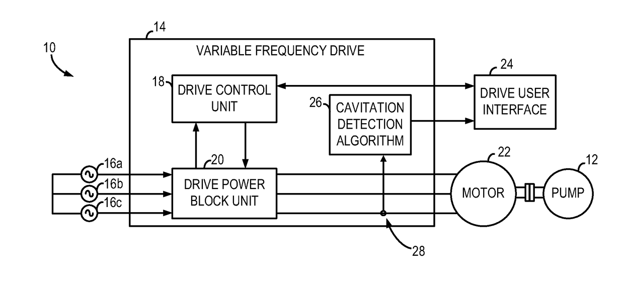
[0021]Several embodiments of the invention are set forth that relate to a system and method of detecting cavitation in pumps driven by an AC motor, which may be fed by a fixed frequency supply or a variable frequency supply. The system monitors motor current and performs a current analysis to generate a reference current to identify a normal operating condition and a fault signature indicative of a cavitation condition.

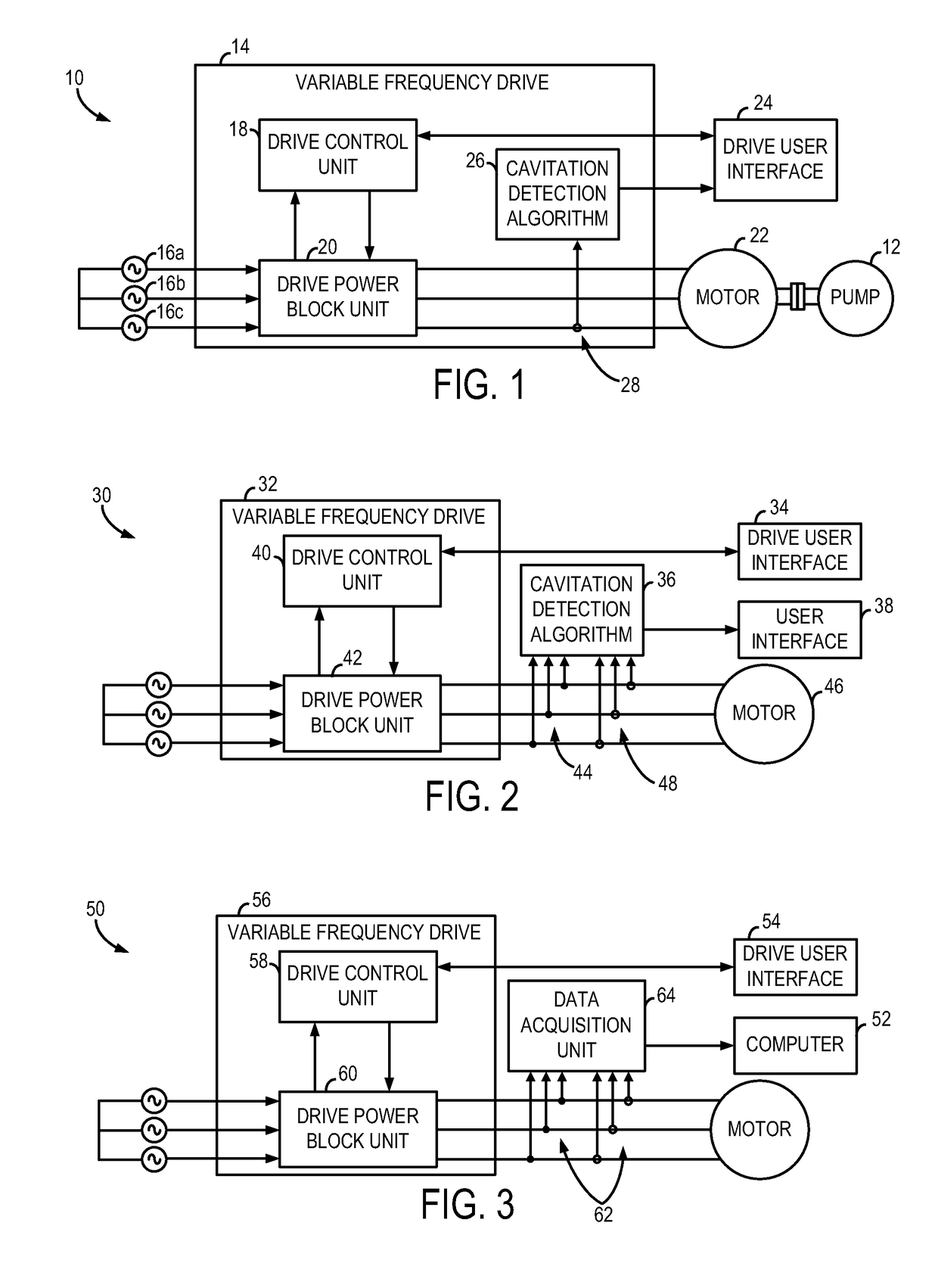
[0022]Referring now to FIG. 1, a general structure of a motor assembly 10 to drive a pump 12 is shown. Motor assembly 10 includes a motor drive 14, which may be configured, for example, as an adjustable or variable speed drive designed to receive a three-phase AC power input power input 16a-16c. Alternatively, motor assembly 10 may be configured to drive a multi-phase motor. A drive control unit 18 is integrated within motor drive14 and functions as part of the internal logic of the drive 14.

[0023]Motor drive 14 also includes a drive power block unit 20, which may, fo...


PUM


Abstract

A system and method for detecting cavitation in pumps for fixed and variable supply frequency applications is disclosed. The system includes a controller having a processor programmed to repeatedly receive real-time operating current data from a motor driving a pump, generate a current frequency spectrum from the current data, and analyze current data within a pair of signature frequency bands of the current frequency spectrum. The processor is further programmed to repeatedly determine fault signatures as a function of the current data within the pair of signature frequency bands, repeatedly determine fault indices based on the fault signatures and a dynamic reference signature, compare the fault indices to a reference index, and identify a cavitation condition in a pump based on a comparison between the reference index and a current fault index.

Description

GOVERNMENT LICENSE RIGHTS[0001]The present invention was made at least in part with Government support under Contract No. DE-FC36-04GO14000, awarded by the United States Department of Energy. The Government may have certain rights in the invention.BACKGROUND OF THE INVENTION[0002]The present invention relates generally to pumps and, more particularly, to a system and method for detecting cavitation in pumps driven by an electric motor.[0003]Cavitation occurs in pumps when the available net positive suction head becomes less than the required head. During cavitation, the suction pressure is less than the vapor pressure of the liquid, thus causing the liquid within the pump to vaporize and form small bubbles of gas. As the vapor bubbles travel away from the eye of the pump, the pressure rises and compresses the vapor, which causes the vapor bubbles to collapse or implode and typically send very strong local shock waves in the fluid. The energy present in the shock waves often damages ...

Claims


Application Information

Patent Timeline
Patent Type & Authority Patents(United States)
IPC IPC(8): G08B21/00F04D29/66F04D15/00
CPCF04D29/669F04D15/0077F04D15/0088
Inventor LU, BINSHARMA, SANTOSH KUMARYAN, TINGDIMINO, STEVEN A.
Owner EATON INTELLIGENT POWER LTD
Why Eureka
Try Eureka