Embedded cant indicator for rifles

a cant indicator and cant body technology, applied in the field of rifle style firearms, to achieve the effect of improved shot accuracy, and high level of precision compensation

Active Publication Date: 2017-10-03
MCREES MULTI SERVICES LLC
View PDF14 Cites 9 Cited by
  • Summary
  • Abstract
  • Description
  • Claims
  • Application Information

AI Technical Summary

Benefits of technology

[0010]The present invention presents an embedded precision level means that provides a true reference to level or plumb allowing for the final cant correction to be made before the shot is taken. The present invention provides the rifle shooter with a tool that greatly enhances “first-round-hit” probabilities and increases overall accuracy. The invention is located so that the rifle shooter does not have to change or disturb his body position to monitor the cant of the rifle.
[0012]The invention presented herein is machined into the assembly on the same plane as the cant axis. The invention location is absolutely true to the Cant Axis because it is machined with computer-aided precision. A set of cant reference gradients is machined into the assembly as well. The Reference gradients allow for duplicating the cant if a “Zero Cant” condition is not achievable. The shooter can perform a quick calculation that formulates the amount of “Point of Aim” adjustment required to successfully engage the target due to the amount of Cant introduced into the rifle. This combination of location, precision machining and calibration feedback allows shooters with much less experience and in situations of duress to greatly improve shot accuracy.
[0013]The invention herein presents methods of using the embedded cant indicator to provide a shooter with an optimized and compensated alignment system that maximizes the accuracy and repeatability of hitting the shooter's target and provides a weapon system that achieves this high level of precision compensation between the target and weapon in a most convenient manner.

Problems solved by technology

This feedback is of critical importance because cant measuring mechanisms of the prior art did not solve the issue of “man-introduced-errors” because the mounting of the cant level indicator is often not performed by a specially trained technician.

Method used


Image

  • Embedded cant indicator for rifles
  • Embedded cant indicator for rifles
  • Embedded cant indicator for rifles

Examples


Embodiment Construction

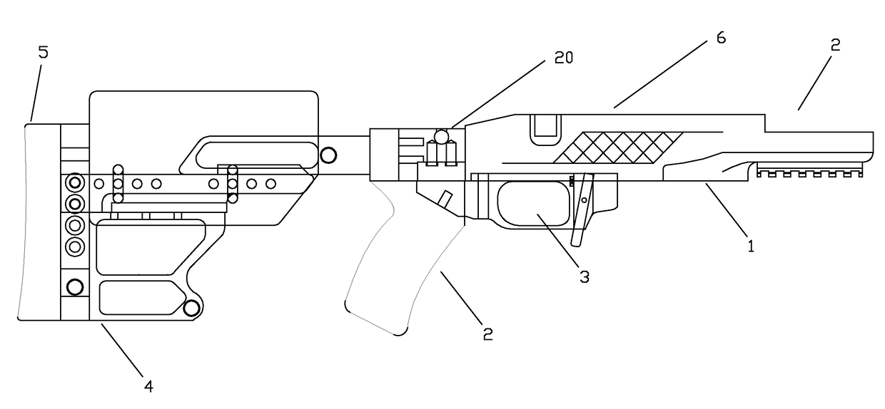
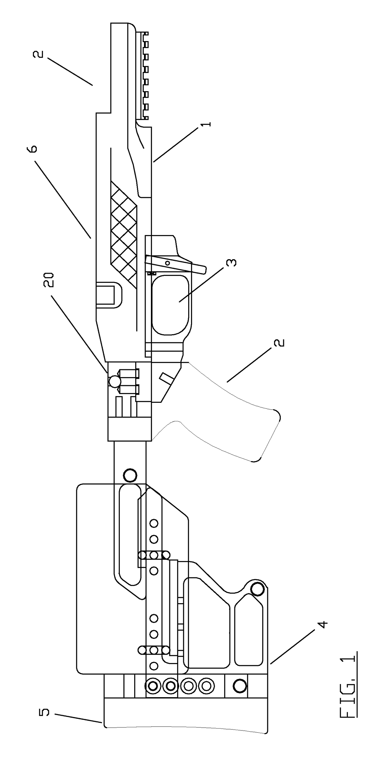
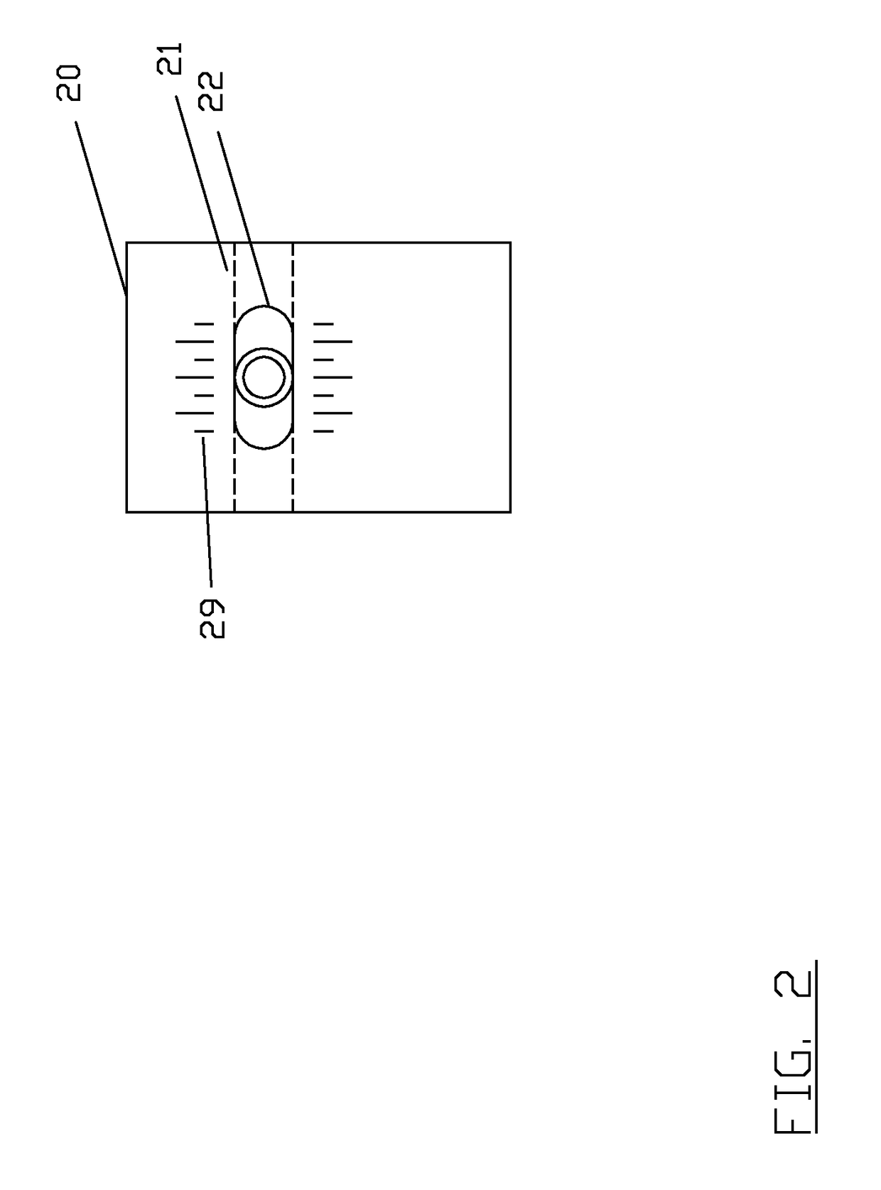
[0018]FIG. 1 illustrates the preferred embodiment of the invention as an element of an overall weapon assembly. This weapon assembly is comprised of multiple parts that are bolted together to provide a functioning rifle. In its most basic form, this particular weapon platform is comprised of a central stock 1, the cant indicator 20, the butt of the rifle 4, a recoil absorbing pad 5. The barrel of the rifle would attach at point 2. If the shooter desired a scope, it would be attached to the central stock at 6. As the shooter holds the weapon and views at the target through the scope in a direction parallel to the axis of the rifle barrel, the cant indication would be obtained by glancing downward at a bubble contained within the cant indicator assembly 20. By using the calibration lines, as will be further described in later Figures, the position of the bubble to the left or right of the center line will indicate the extent with which the rifle is tilted about the axis of the barrel....


PUM


Abstract

A device comprised of bubble level inserted into and secured within a cavity located above the rifle grip and behind the barrel to facilitate the measurement and compensation of the rifle's cant while lining up the rifle's sights. The device is precision machined to allow the bubble to be aligned with the axis of the barrel to produce a true “zero-cant” condition. Graduation markings are placed on either left or right of the bubble level to allow the user to better judge the relative degree of cant. Methods of using the embedded cant indicator for precision shooting are presented.

Description

CROSS-REFERENCES[0001]This is a Divisional Application from U.S. nonprovisional application Ser. No. 14 / 154,214 and claims all priority to the aforementioned application.FIELD OF THE INVENTION[0002]This invention relates generally to rifle style firearms, and particularly concerns both apparatus and methods for readily and precisely determining the cant of the rifle relative to the target such that the shooter can make appropriate aim adjustments to improve the probability of hitting the target. The location of the cant measurement device is designed to facilitate the shooters assessment of the rifle's cant when viewing other sighting means on the rifle.BACKGROUND OF THE INVENTION[0003]Accuracy in placing a projectile onto a target using a rifle requires the shooter to determine three primary elements: 1) distance to the target, 2) the incline of the projectile as it leaves the rifle, and 3) the cant of the rifle at the moment the projectile leaves the rifle. The rifle cant is defin...

Claims


Application Information

Patent Timeline
Patent Type & Authority Patents(United States)
IPC IPC(8): F41G1/44F41G1/54F41C27/00
CPCF41G1/44F41G1/54F41C27/00F41C23/22
Inventor MCREE, SCOTT
Owner MCREES MULTI SERVICES LLC
Why Eureka
Try Eureka