Solar power tower receiver

a solar power tower and receiver technology, applied in the direction of solar heat collectors with working fluids, solar heat collectors for particular environments, solar radiation concentration, etc., can solve the problems of reducing the efficiency of the receiver, and reducing the optimum operating point of a power plant, so as to achieve the effect of improving efficiency

Active Publication Date: 2017-10-10
STELLENBOSCH UNIVERSITY
View PDF12 Cites 1 Cited by
  • Summary
  • Abstract
  • Description
  • Claims
  • Application Information

AI Technical Summary

Benefits of technology

[0016]Additional features of the invention provide for unpressurized louvers, panes, or rods typically of glass or quartz glass, to be positioned in front of the absorber tubes to reflect radiation received from a heliostat field inwards into the chamber and towards the absorber tubes and to inhibit the escape of re-radiation energy emitted by absorber tubes, especially those nearer the window; for the unpressurized transparent louvers, panes or rods to be arranged so as to form a non-continuous front profile directed generally towards the heliostat field with individual louvers, panes or rods having oblique frontal surfaces such that reflected rays travel towards the inside of the chamber of the receiver; and for the receiver to include multiple groups of unpressurized louvers, panes or rods arranged to provide a leading group in which the temperature of the louvers, panes or rods is, under operating conditions, maintained at a level low enough to reduce thermal losses, especially reflection and radiation losses.
[0023]A combined Rankine / Brayton cycle utilizes the thermal energy that remains in the outlet air stream from the Brayton cycle gas turbine to generate steam in a separate Rankine cycle. Thus the combined Rankine / Brayton cycle may be considered to have an enhanced efficiency.

Problems solved by technology

Receiver efficiency of a solar power receiver greatly affects the optimum operating point of a power plant and reduced receiver efficiency causes a decrease in the optimum operating point of a power plant.
Receiver efficiency is typically reduced due to reflection losses, convection losses and radiation losses from a solar power receiver.
Reflection losses occur if a surface at the receiver is incapable of absorbing or transmitting an incident solar ray.
Convection losses are experienced if a small air particle gains energy from a surface at higher temperature, and carries the energy away from the receiver.
However, convection and radiation losses were too high.
As a consequence of the physical characteristics of suitable quartz glass, and the fact that it needs to be cooled during use, certain difficulties present themselves in the use of such an arrangement.
However, a limitation of an open volumetric receiver is that it can only be used in a Rankine cycle for the production of electrical energy.
Pressurized air cannot be contained and thus cannot be used as a working fluid.

Method used


Image

  • Solar power tower receiver
  • Solar power tower receiver
  • Solar power tower receiver

Examples


Embodiment Construction

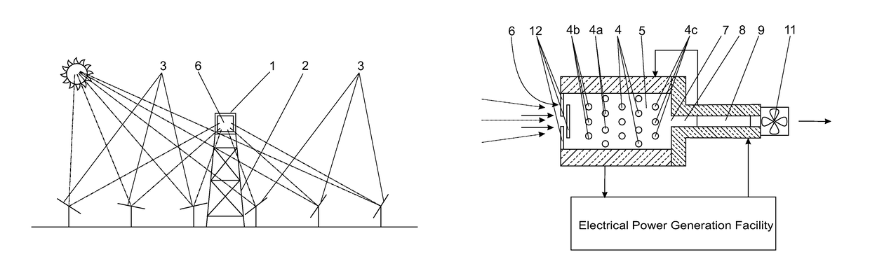
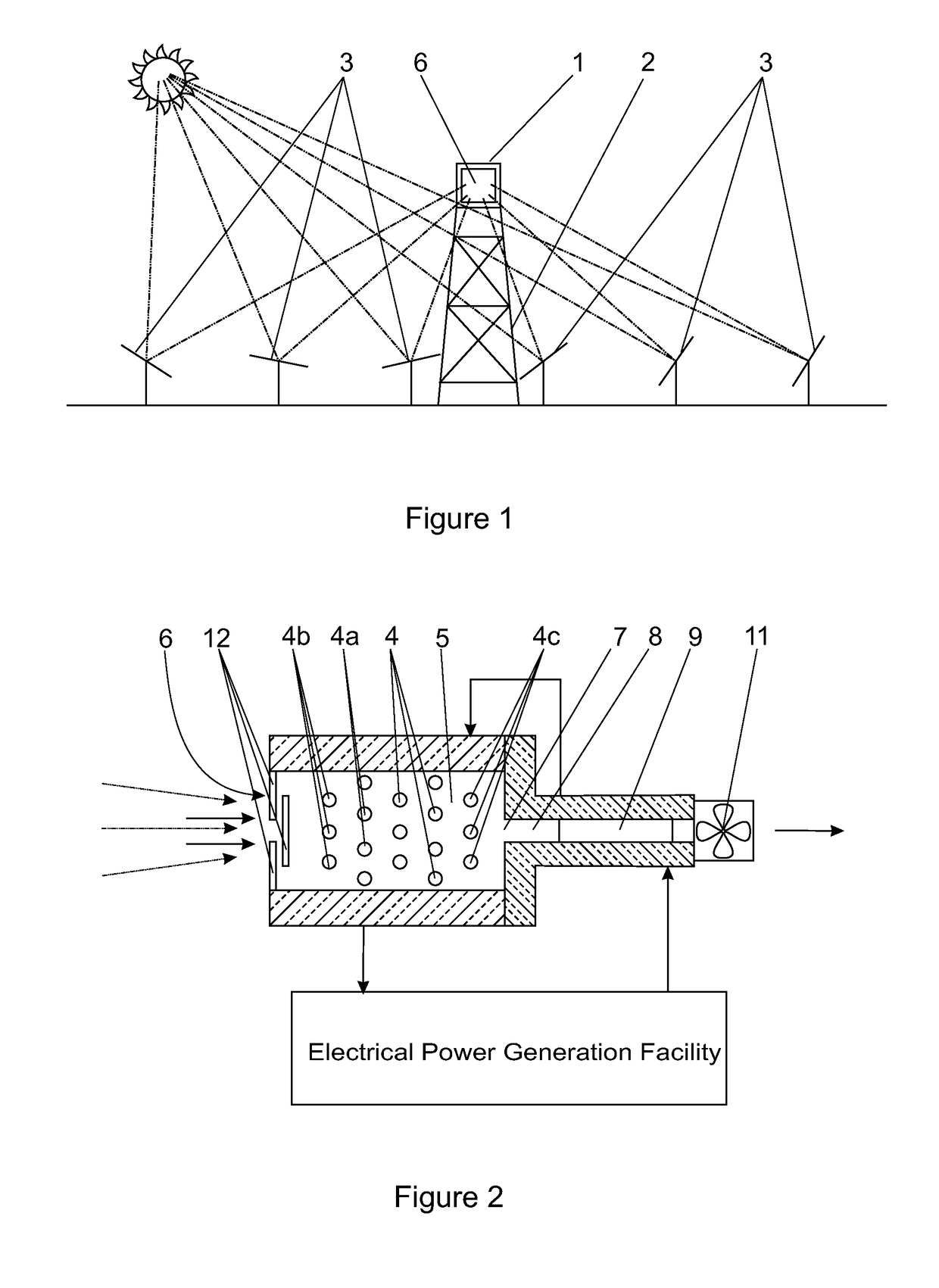
[0036]In the embodiment of the invention illustrated in the drawings a central receiver (1) for a solar power facility is mounted on the upper end of a tower (2) in a field of heliostats (3). The central receiver comprises an arrangement of transverse heat absorber tubes (4) located in a chamber (5) having a window (6) that, in use, is to receive solar radiation reflected by the heliostat field.

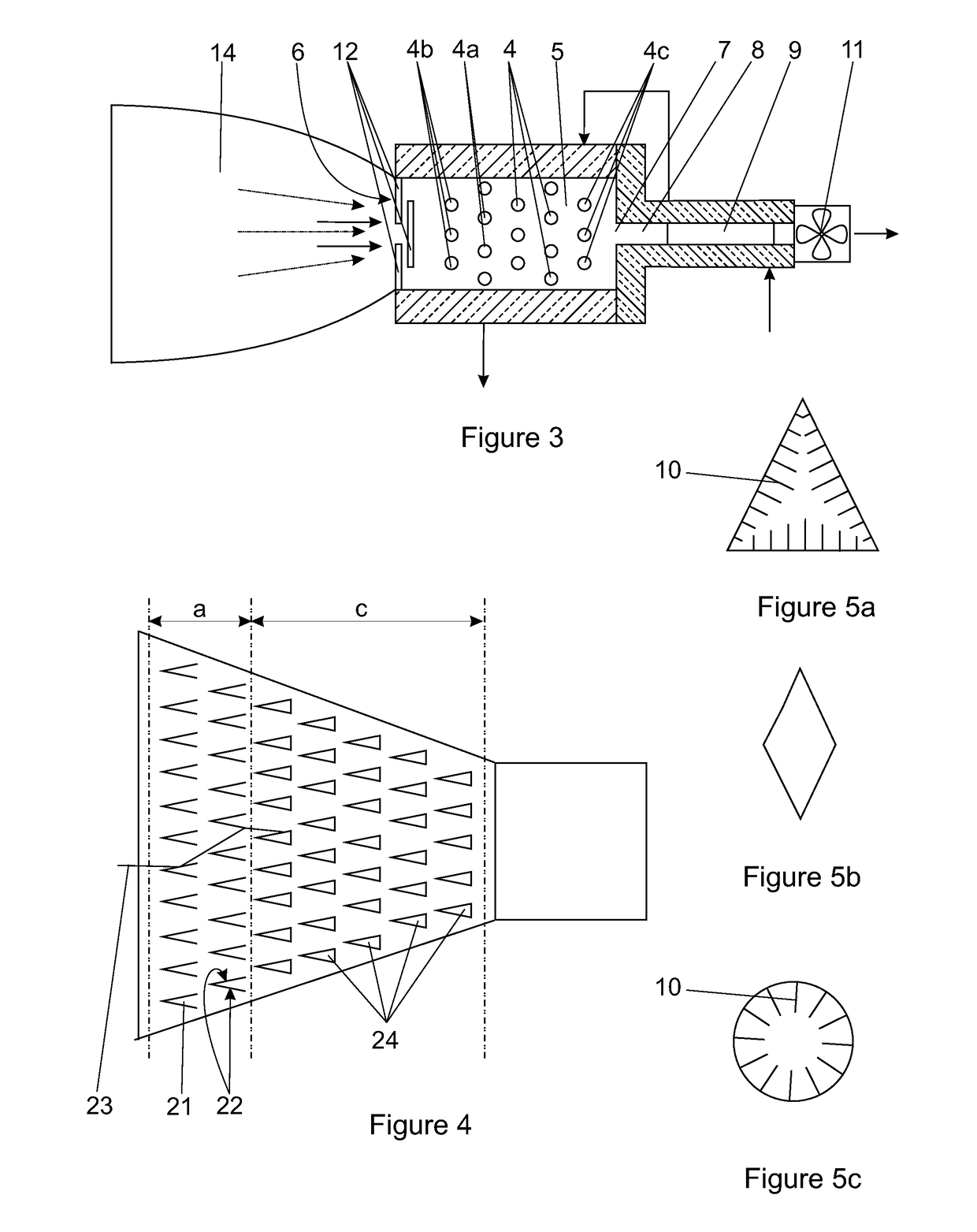
[0037]The window forms an air inlet for ambient air at atmospheric pressure to flow past and around the heat absorber tubes and an air outlet (7) is provided in an opposite region of the chamber such that air flows in through the window, past and over the absorber tubes, and out through the outlet.

[0038]The chamber (5) may be square in cross-section and it can be of any suitable shape from the window to the outlet such as rectangular, pyramidal, conical or parabolic. The angles for a pyramidal, conical or parabolic-shape of cavity will depend largely on the acceptance angle of the receiver.

[0...


PUM


Abstract

A central receiver for a solar power facility is provided comprising an arrangement of heat absorber tubes located in a chamber having a window that, in use, is to receive solar radiation reflected by a heliostat field. The heat absorber tubes extend transversely relative to the window and are connected into a working fluid circuit. The window forms an atmospheric air inlet and the chamber has an outlet in a region opposite the window. An air flow promoting fan induces a flow of atmospheric air inwards through the window, past the absorber tubes; and through the outlet. The receiver preferably includes multiple rows of unpressurized louvers or panes having oblique frontal surfaces such that reflected rays travel into the chamber and provide a leading row in which the temperature of the louvers is, under operating conditions, maintained at a level low enough to reduce thermal reflection and radiation losses.

Description

RELATED APPLICATIONS[0001]This application is a 35 U.S.C. §371 filing of International Application No. PCT / IB2013 / 053287, filed Apr. 25, 2013, which claims priority to South African Patent Application No. 2012 / 03064, filed Apr. 26, 2012, each of which is incorporated herein by reference in its entirety.FIELD OF THE INVENTION[0002]This invention relates to a solar power tower receiver of the general type that is used in large solar power plants in which incoming solar radiation is concentrated on one or more central receivers via multiple tracking mirrors called heliostats. The central receivers are typically located on one or more towers that are positioned generally at the center of a heliostat field, at least in the sense of a central receiver servicing multiple heliostats. A central receiver serves to convert the solar radiation to thermal energy that is typically absorbed by a heat transfer fluid and used, either immediately, or after a period of thermal storage, in a power gene...

Claims


Application Information

Patent Timeline
Patent Type & Authority Patents(United States)
IPC IPC(8): F24J2/10F24J2/04F24J2/07F24J2/24F24S10/70F24S20/20F24S23/70
CPCF24J2/10F24J2/0477F24J2/0488F24J2/24F24J2/07Y02E10/44Y02E10/41F24S10/20F24S70/60F24S20/20F24S23/70F24S10/70F24S80/50F24S10/80Y02E10/40
Inventor KRETZSCHMAR, HOLGERGAUCHE, PAUL
Owner STELLENBOSCH UNIVERSITY
Why Eureka
Try Eureka