Persistent memory descriptor

a persistent memory and descriptor technology, applied in the field of memory systems, can solve the problems of insufficient conventional implementation of moving information stored at the nvm to volatile memory, relatively high cost and data loss risk, and achieve the effect of reducing or eliminating the need for software intervention of large dma streams between dram memory and persistent memory, reducing the need for large dma streams, and reducing the need for large gaps

Active Publication Date: 2017-10-10
RAMBUS INC
View PDF3 Cites 4 Cited by
  • Summary
  • Abstract
  • Description
  • Claims
  • Application Information

AI Technical Summary

Benefits of technology

[0009]Embodiments of the present invention provide many advantages over conventional techniques. Among other things, by using descriptor fields to identify DRAM target location, the needs of software intervention of large DMA streams between DRAM memory and persistent memory is substantially reduced or eliminated. In addition, the use of descriptor fields enables fast save / restore execution through larger DMA transfers. It helps to eliminate returned data queues for ordering purposes, which results in smaller gaps between data units. In addition, out of order return of data streams from persistent memory require no intervention from a controlling processor as the embedded descriptor fields provide the control information to return data to its proper location in DRAM memory. In addition, embodiments of the present invention can be easily implemented and adopted into existing systems. For example, DMA controllers can be programmed to create and use descriptor fields for save and restore operations. There are many other advantages as well.

Problems solved by technology

Yet, such storage technologies can have a relatively high cost and risk of data loss (e.g., on power loss).
Among other things, moving information stored at the NVM to volatile memory can be inadequate with conventional implementations, and improved techniques are desired.

Method used


Image

  • Persistent memory descriptor
  • Persistent memory descriptor
  • Persistent memory descriptor

Examples


Embodiment Construction

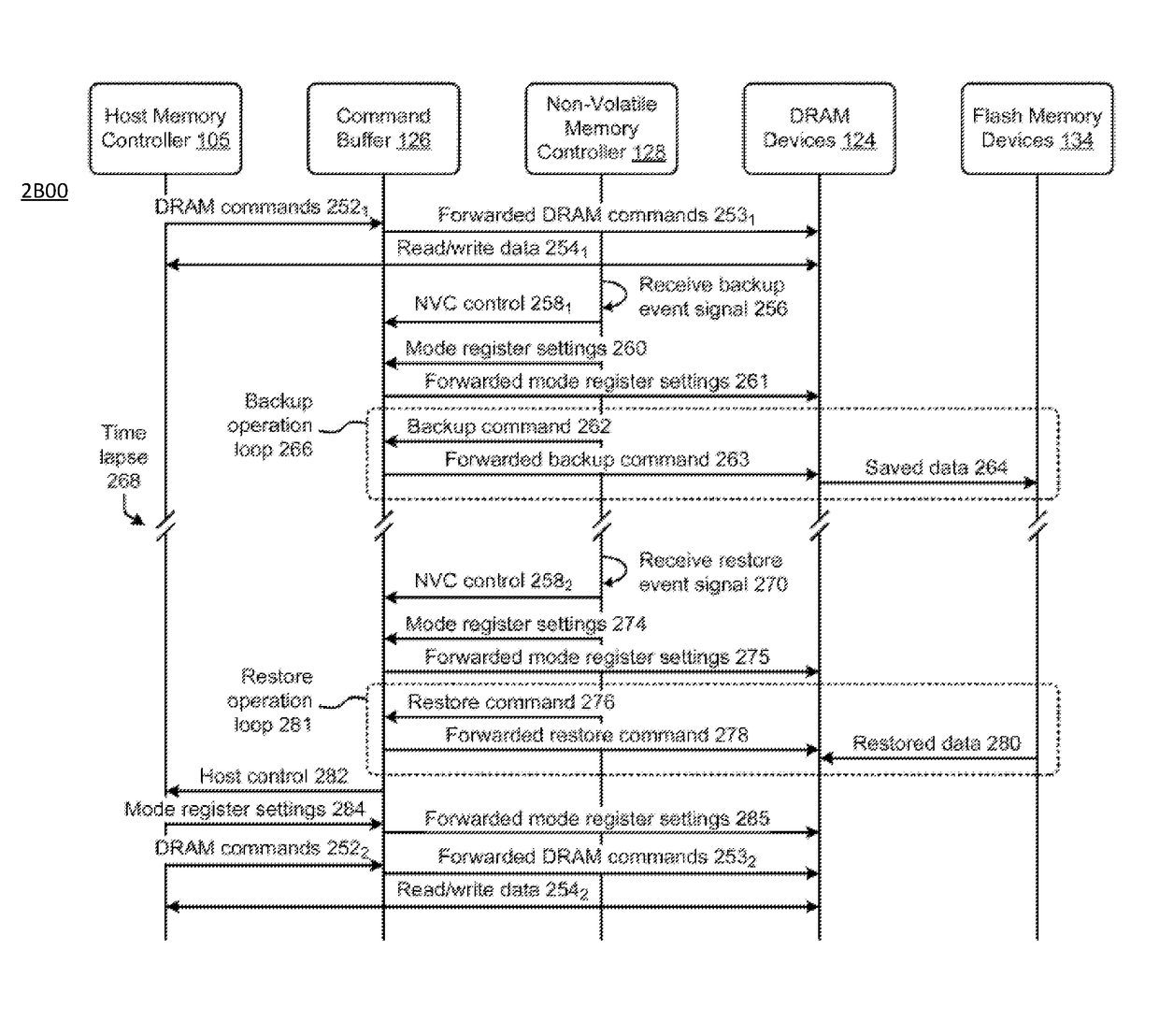
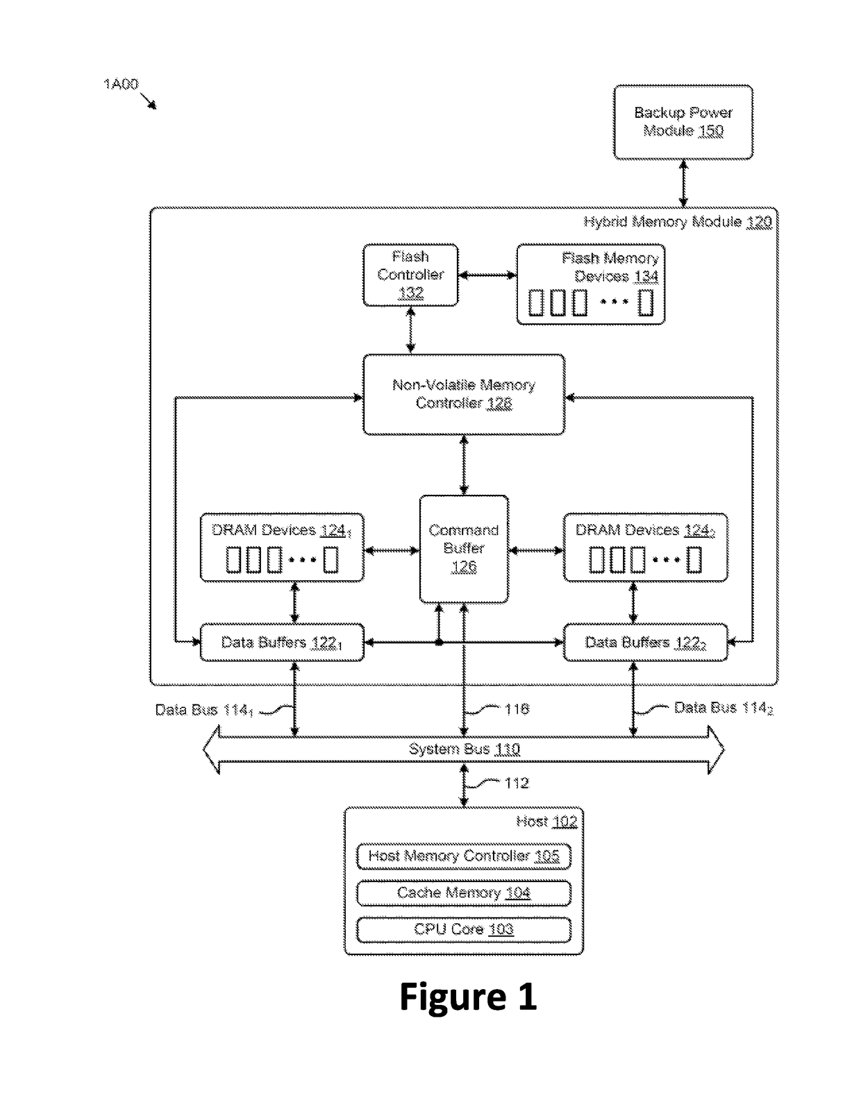
[0017]The present invention is directed to memory systems. More specifically, embodiments of the present invention provide a memory system with a volatile memory, a persistent memory, and a controller. In a save operation, the controller copies contents of the volatile memory to the persistent memory as data units with their corresponding descriptor fields, where the descriptor fields include address information. In a restore operation, the controller copies data units from the persistent memory to their corresponding locations based on addresses stored at descriptor fields. There are other embodiments as well.

[0018]As mentioned above, conventional techniques for NVDIMM systems have been inadequate. A typical function of a NVDIMM system is to have the persistent memory (e.g., NVM) backup the data stored at the persistent memory (e.g., in the events of power failure, hibernation mode, etc.), and the data stored at the persistent memory is copied back to the volatile memory (or someti...


PUM


Abstract

The present invention is directed to memory systems. More specifically, embodiments of the present invention provide a memory system with a volatile memory, a persistent memory, and a controller. In a save operation, the controller copies contents of the volatile memory to the persistent memory as data units with their corresponding descriptor fields, where the descriptor fields include address information. In a restore operation, the controller copies data units from the persistent memory to their corresponding locations based on addresses stored at descriptor fields. There are other embodiments as well.

Description

BACKGROUND OF THE INVENTION[0001]The present invention is directed to memory systems.[0002]As the massive volumes of electronically stored and transmitted data (e.g., “big data”) continue to increase, so does the need for electronic data storage that is reliable and cost effective, yet quickly accessible (e.g., low latency). Specifically, more computing applications are requiring that increasingly larger data sets be stored in “hot” locations for high speed access. Certain non-volatile memory (NVM) storage technologies, such as magnetic hard disk drives (HDDs), can provide a reliable, low cost storage solution, yet with relatively high access latencies. Such storage technologies might be used for large volumes of data in “cold” locations that are not often accessed (e.g., data warehouses, archives, etc.). Other volatile or “dynamic” memory storage technologies, such as dynamic random access memory (DRAM), provide lower access latencies, and might be used in “hot” locations near a co...

Claims


Application Information

Patent Timeline
Patent Type & Authority Patents(United States)
IPC IPC(8): G06F12/00G06F12/02G06F11/14G06F12/0802G06F3/06
CPCG06F3/0619G06F3/065G06F3/0685G06F12/0802G06F11/1446G06F12/0238G06F12/0246G06F3/0608G06F11/1448G06F2212/60G06F12/0868G06F2212/1024G06F2212/205G06F2212/214G06F2212/313G06F11/1441G06F11/0751G06F13/28
Inventor SHALLAL, AWSWILLIAMS, COLLINSKUNKEL, DANWOLF, WILLIAM
Owner RAMBUS INC
Why Eureka
Try Eureka