
Over-the air test

a test and air technology, applied in the field of over the air testing, can solve the problems of interference with the radio connection, echoes in the chamber, and different durations of signal strength and fades, and achieve the effect of more distortion and accurate results

Active Publication Date: 2017-10-10
KEYSIGHT TECH SINGAPORE (SALES) PTE LTD
View PDF11 Cites 0 Cited by
  • Summary
  • Abstract
  • Description
  • Claims
  • Application Information

AI Technical Summary

Benefits of technology

The invention improves accuracy in an OTA chamber and allows for better use of an OTA chamber that has more echoes and distortion.

Problems solved by technology

These changes may cause variation in signal strength and fadings of different durations.
In addition, noise and interference due to other transmitters interfere with the radio connection.
Often the OTA antennas themselves cause echoes in the chamber.
The unwanted reflections cause distortion to the emulated radio channel and deteriorate the quality of the emulation.
On the other hand, it is technically very challenging to make the OTA chamber anechoic enough for the radio channel emulation, particularly with a moderate budget.

Method used


Image

  • Over-the air test
  • Over-the air test
  • Over-the air test

Examples


Embodiment Construction

[0027]Exemplary embodiments will be described more fully hereinafter with reference to the accompanying drawings, in which some embodiments are shown. Although the specification may refer to “an”, “one”, or “some” embodiment(s) in several locations, this does not necessarily mean that each such reference is to the same embodiment(s), or that the feature only applies to a single embodiment. Single features of different embodiments may also be combined to provide other embodiments. Therefore, all words and expressions should be interpreted broadly and they are intended to illustrate, not to restrict, each embodiment.

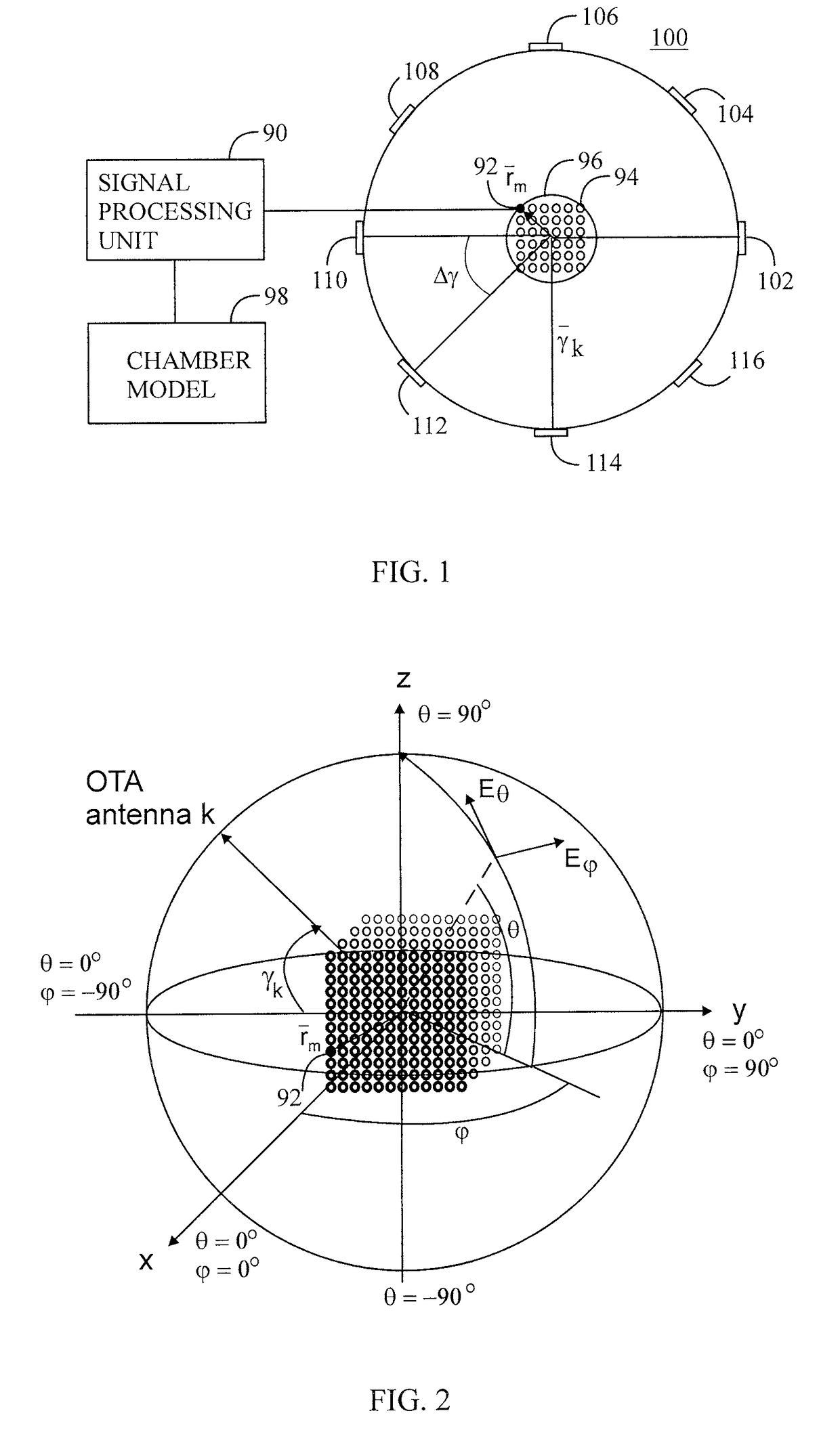
[0028]This application relates to quantification and compensation of reflections, scattering and other non-idealities within an OTA chamber in a MIMO OTA test set-up.

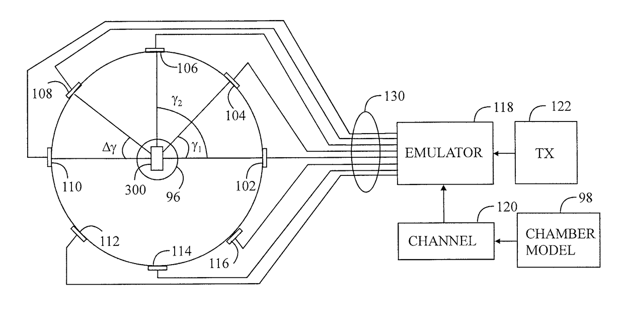
[0029]FIG. 1 presents basic principles of calibration measurement in the OTA chamber two dimensionally. Although the OTA chamber 100 should cause no effect to the emulated radio channel, the emulated radio cha...


PUM


Abstract

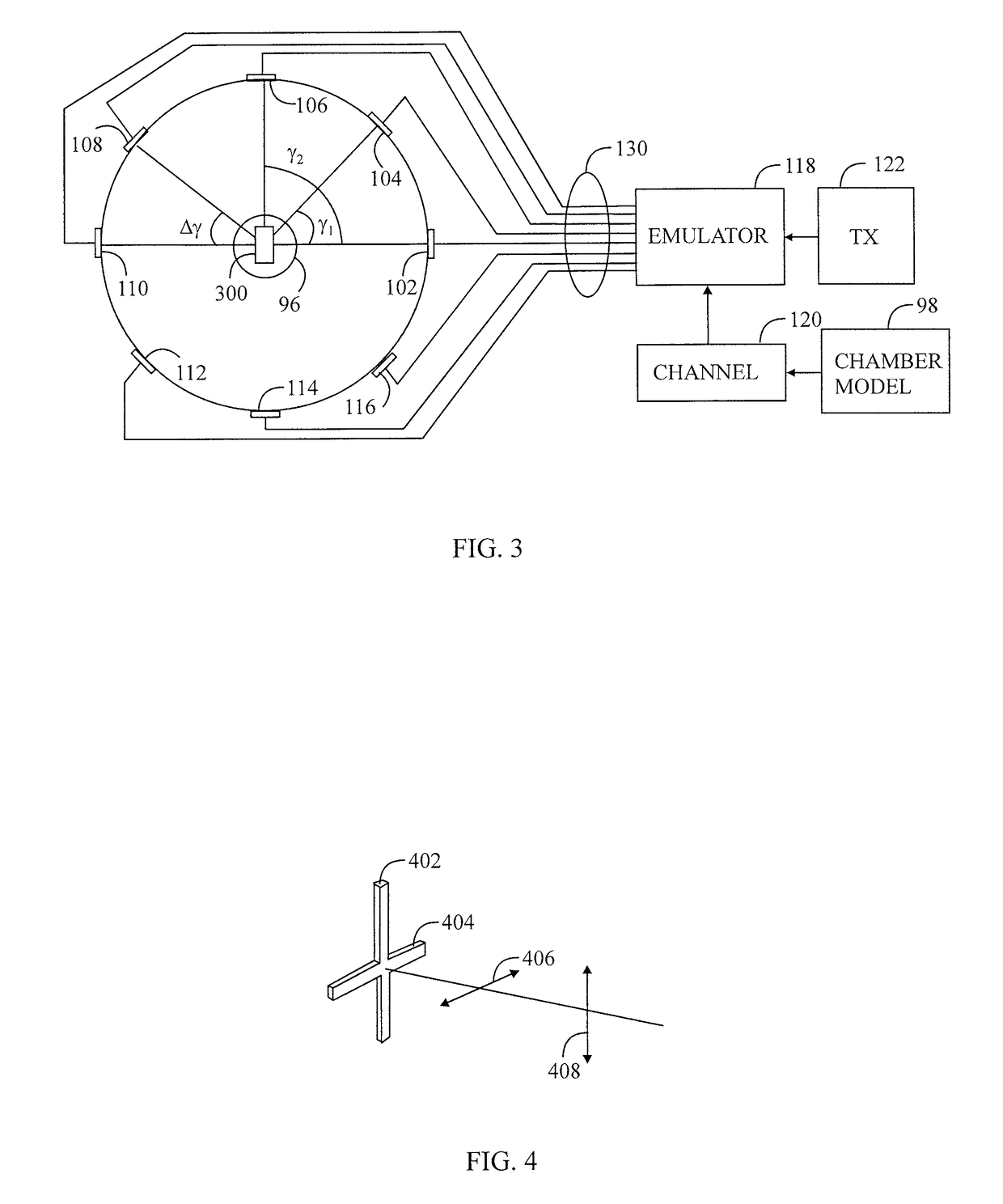
A radio channel generator has a radio channel model predistorted on the basis of a predetermined chamber model. An emulator receives the weights of the radio channel model predistorted on the basis of the chamber model. A transmitter feeds a communication signal to the emulator. The emulator weights the communication signal with the radio channel model predistorted on the basis of the chamber model. The over-the-air antennas receive the weighted communication signal and transmit it to a device under test. The chamber model is based on a simulation or a measurement. The chamber model takes into account undesired interactions in the over-the-air chamber for cancelling them during the radio channel emulation.

Description

CROSS-REFERENCE TO RELATED APPLICATION[0001]This application is a National Phase application of International Application No. PCT / FI2011 / 050637, filed Jul. 6, 2011, which is incorporated by reference herein in its entirety.BACKGROUND[0002]Field[0003]The invention relates to over-the-air testing of a device in an anechoic chamber.[0004]Description of the Related Art[0005]When a radio frequency signal is transmitted from a transmitter to a receiver, the signal propagates in a radio channel along one or more paths having different angles of arrivals, signal delays, polarizations and powers. Also a frequency may change due to the Doppler effect. These changes may cause variation in signal strength and fadings of different durations. In addition, noise and interference due to other transmitters interfere with the radio connection.[0006]A transmitter and a receiver can be tested using a radio channel emulator emulating real circumstances. In a digital radio channel emulator, a radio chann...

Claims


Application Information

Patent Timeline
Patent Type & Authority Patents(United States)
IPC IPC(8): G06F17/50H04B15/00G01R29/08H04B17/00H01Q3/26H04B17/391H04B17/21
CPCH04B15/00G01R29/0821H01Q3/267H04B17/391H04B17/3912H04B17/0085H04B17/3911H04B17/21
Inventor KYOSTI, PEKKALAITINEN, TOMMI
Owner KEYSIGHT TECH SINGAPORE (SALES) PTE LTD
Learn More