Motor controller and fan system comprising the same

a technology of motor controller and fan system, which is applied in the direction of liquid fuel engines, casings/cabinets/drawers, casings/cabinets/drawers details, etc., can solve the problems of low reliability of motor controller of such structure, poor heat dissipation performance, hidden dangers, etc., to reduce the temperature of the control circuit board, improve the reliability of the operation of the motor controller, and effectively protect the electronic components

Active Publication Date: 2017-10-10
ZHONGSHAN BROAD OCEAN
View PDF6 Cites 2 Cited by
  • Summary
  • Abstract
  • Description
  • Claims
  • Application Information

AI Technical Summary

Benefits of technology

[0007]In view of the above-described problems, it is one objective of the invention to provide a motor controller and a fan system comprising the same. The motor controller has a simple structure, convenient installation, excellent heat dissipation performance, high efficiency and reliability. The fan system has a simple and compact structure, convenient installation, good heat dissipation performance, and high reliability.

Problems solved by technology

Limited by the space, the motor controller generally has a small volume, thereby resulting in poor heat dissipation performance; besides, heat quantity produced by the motor is accumulated at the bottom part of the load box.
Because the control circuit board is mounted inside the sealed control box, when the temperature therein increases and the heat quantity in the control box is difficult to dissipate, the normal operation of the control circuit board will be seriously affected.
Thus, the motor controller of such structure has low reliability and hidden dangers.
Some manufacturers have adopted methods of arranging cooling ribs or vent holes on an outer surface of the control box to improve the heat dissipation performance of the motor controller, but such motor controller is troublesome in assembly and the heat dissipation effect thereof is not ideal.
Since the motor is far away from the motor controller, a lead wire demanded for connection is so long that a large space is occupied; furthermore, it is troublesome to connect the long lead wire, faults easily occur, and hidden dangers exist.
However, since the motor controller is a sealed structure, poor dissipation performance of the motor controller is resulted.
After a long term operation of the motor controller, the temperature inside the motor controller increases, so that the normal operation of the motor controller is affected, and faults easily occur during the operation of the motor under the control of the motor, thereby resulting in low reliability.

Method used


Image

  • Motor controller and fan system comprising the same
  • Motor controller and fan system comprising the same
  • Motor controller and fan system comprising the same

Examples


example 1

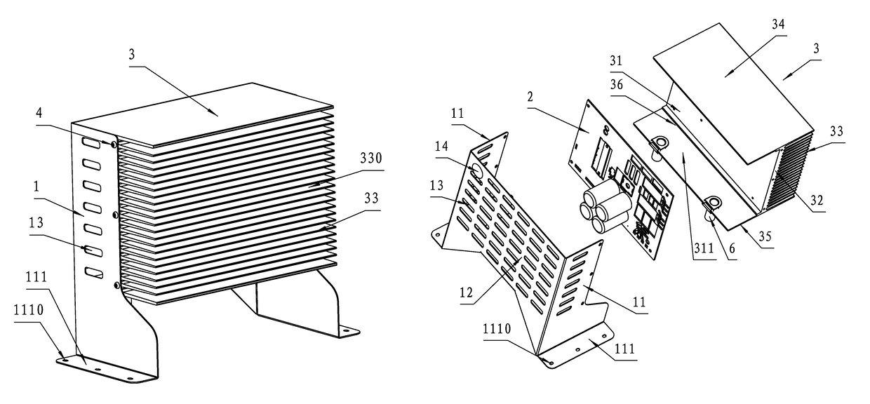
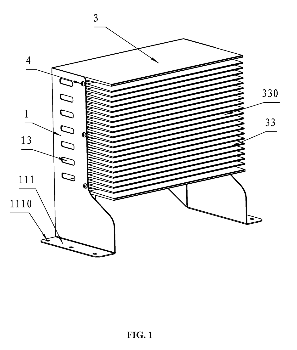
[0037]As shown in FIGS. 1-6, a motor controller comprises: a supporting frame 1, a control circuit board 2, and a control box 3. The control box 3 is provided with a cavity 31. The control circuit board 2 is disposed on a base plate 32 in the cavity 31. A plurality of fins 33 is disposed outside the cavity 31 on an outer side surface of the base plate 32. Cooling ducts 330 are formed between adjacent fins 33. The control box 3 is fixed on the supporting frame 1.

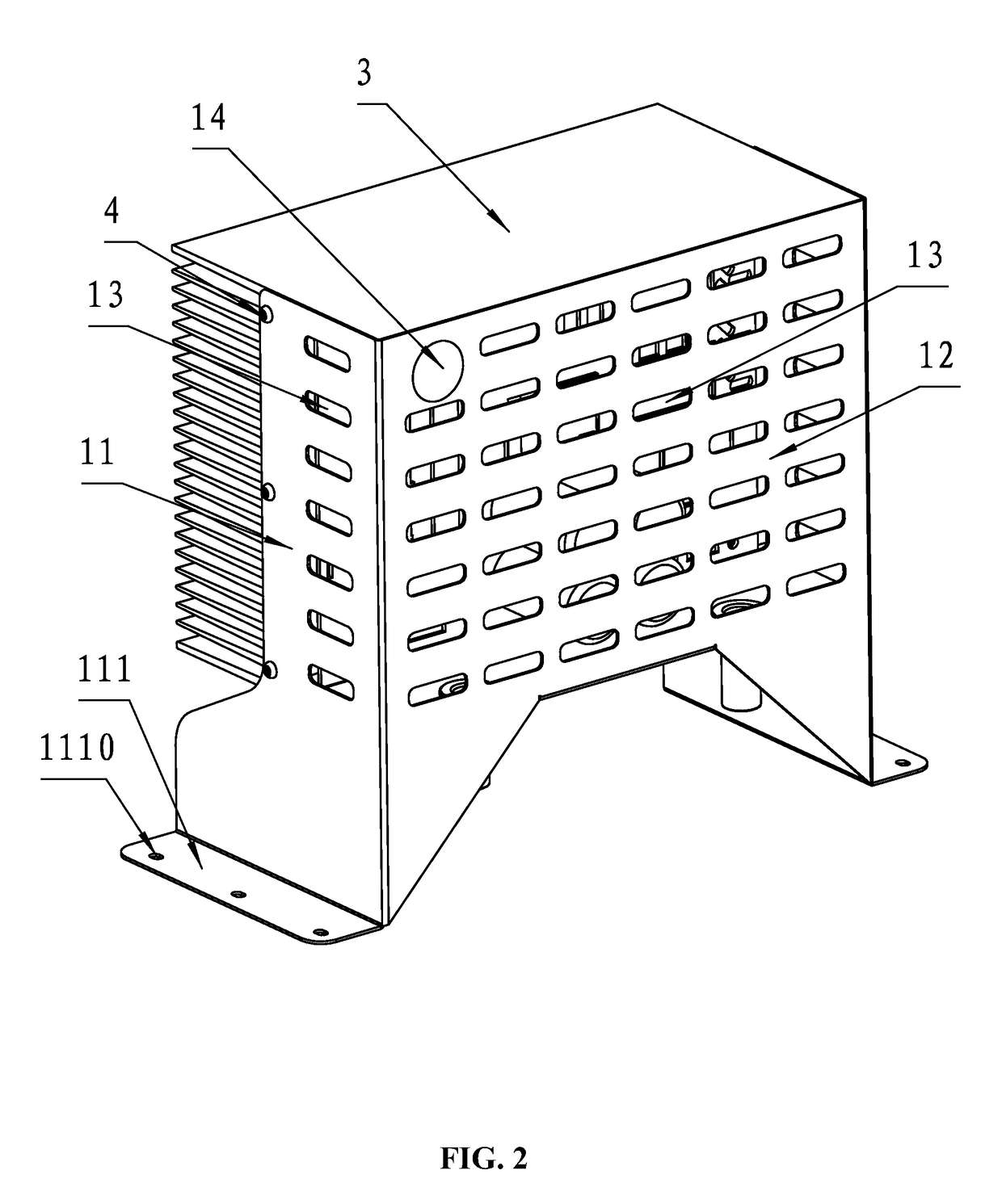
[0038]The control box 3 comprises: the base plate 32, and an upper plate 34 and a lower plate 35 extended from two ends of the base plate 32 to a same side. The upper plate 34, the base plate 32, and the lower plate 35 form the cavity 31, side openings at two sides of the cavity 31, and an upper opening 31 at a top of the cavity 31. The supporting frame 1 comprises two supporting plates 11 and a connecting plate 12 connected to the two supporting plates 11. The connecting plate 12 shields the upper opening 31 of the control b...

example 2

[0045]As shown in FIGS. 7-8, a fan system comprises: a volute 7, a wind wheel, a motor 8, and a motor controller 9. An inner cavity 71 is disposed in the volute 7. An end face of the volute 7 is provided with an air inlet 72. A side face of the volute 7 is provided with a first air outlet 73. The motor 8 is disposed outside the air inlet 72 of the volute 7. A rotating shaft 81 of the motor 8 is inserted into the inner cavity 71 and connected to the wind wheel. The motor controller 9 is disposed nearby the motor 8. The motor controller 9 is in electric connection with the motor 8 and controls operation of the motor 8. The motor controller 9 comprises: a supporting frame 1, a control circuit board 2, and a control box 3. The control box 3 is provided with a cavity 31. The control circuit board 2 is disposed on a base plate 32 in the cavity 31. A plurality of fins is disposed outside the cavity 31 on an outer side surface of the base plate 32. Cooling ducts 330 are formed between adjac...


PUM


Abstract

A motor controller, including: a supporting frame, a control circuit board, and a control box. The control box includes: a cavity, a base plate, and a plurality of fins. The control circuit board is disposed on the base plate in the cavity. The fins are disposed outside the cavity on an outer side surface of the base plate. Cooling ducts are formed between adjacent fins. The control box is fixed on the supporting frame.

Description

CROSS-REFERENCE TO RELATED APPLICATIONS[0001]This application is a continuation-in-part of International Patent Application No. PCT / CN2013 / 085760 with an international filing date of Oct. 23, 2013, designating the United States, now pending, and further claims priority benefits to Chinese Patent Application No. 201320387505.9 filed Jun. 29, 2013. The contents of all of the aforementioned applications, including any intervening amendments thereto, are incorporated herein by reference.BACKGROUND OF THE INVENTION[0002]Field of the Invention[0003]The invention relates to a motor controller and a fan system comprising the same.[0004]Description of the Related Art[0005]A typical motor controller includes a control box and a control circuit board. The control box is provided with a cavity, and the control circuit board is disposed in the cavity of the control box. The motor controller is generally disposed at a bottom part of a load box. Limited by the space, the motor controller generally...

Claims


Application Information

Patent Timeline
Patent Type & Authority Patents(United States)
IPC IPC(8): H05K7/20F04D27/00F04D25/06H05K5/02F04D29/58H05K5/00
CPCH05K7/20418F04D25/06F04D25/068F04D27/004F04D29/5813H05K5/0234F04D27/00H05K5/0026Y02B30/70
Inventor TANG, SONGFAZENG, CHONGSHENGFENG, JIANLONGJI, ZHONGYINGMEI, YOUPING
Owner ZHONGSHAN BROAD OCEAN
Why Eureka
Try Eureka