Accumulator

a technology of accumulator and accumulator body, which is applied in the direction of mechanical machines/dredgers, percussive tools, and percussive tools portable, etc., can solve the problems of inability to assist in cyclic operations with the converse requirements, inability to meet the requirements of cyclic operations with non-constant power, and inability to meet the requirements of cyclic operations. to achieve the effect of enhancing performance and/or efficiency

Active Publication Date: 2017-10-17
ROBSON ANGUS PETER
View PDF42 Cites 9 Cited by
  • Summary
  • Abstract
  • Description
  • Claims
  • Application Information

AI Technical Summary

Benefits of technology

[0066]There is a limit to the velocity at which the hammer weight may be lifted without causing damage and wear to the upper portion of the hammer assembly during deceleration of the hammer weight before being driven downwards. However, any additional drive force applied to the hammer weight when falling downwards under gravity is highly desirable to improve the impacting effect. Consequently, an accumulator may be incorporated in the hammer drive mechanism, whereby any un-utilised available power from hydraulic drive mechanism during lifting may be used to store energy in the accumulator, which is then released when the hammer weight is driven down to achieve a greater energy impact. The use of such an accumulator thus enables either a lighter hammer weight to be used to achieve the same impact energy of a heavier hammer or increased impact energy for the same hammer weight.
[0176]It will be seen therefore that the present invention provides an accumulator capable of enhancing the performance and / or efficiency of a variety of cyclically and / or reciprocating machinery including powered drop hammers, compactors, feeders, sawmills, wood splitters, compaction equipment, plastic moulding equipment, agricultural hay balers, concrete breakers, slewing mechanisms in excavators and cranes.

Problems solved by technology

There are inherent restrictions in any hydraulic system powered by a pump configured to provide a predetermined continuous power.
While a more powerful pump will have the capacity to pump hydraulic fluid faster at a given pressure, it also requires more energy.
Thus, it can be seen that prior art accumulators are primarily directed at improving consistency of power output by taking some of the peak power of a cyclic operation and re-introducing it into portions of the cycle with a lower-power availability However, this does not assist in cyclic operations with the converse requirements, i.e. cyclic operations with non-constant power requirements.
In particular, prior art accumulators do not assist cyclic operations where there is unutilised available power during portions of the cycle, whilst additional power is highly desirable at other portions of the cycle.

Method used


Image

  • Accumulator
  • Accumulator
  • Accumulator

Examples


Embodiment Construction

[0194]

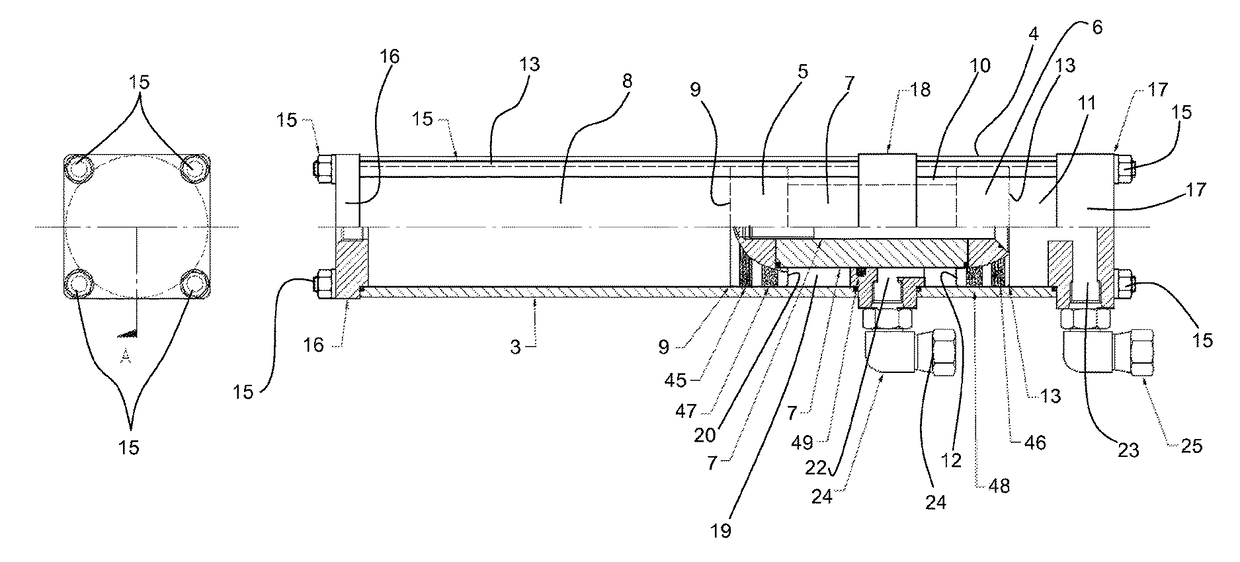
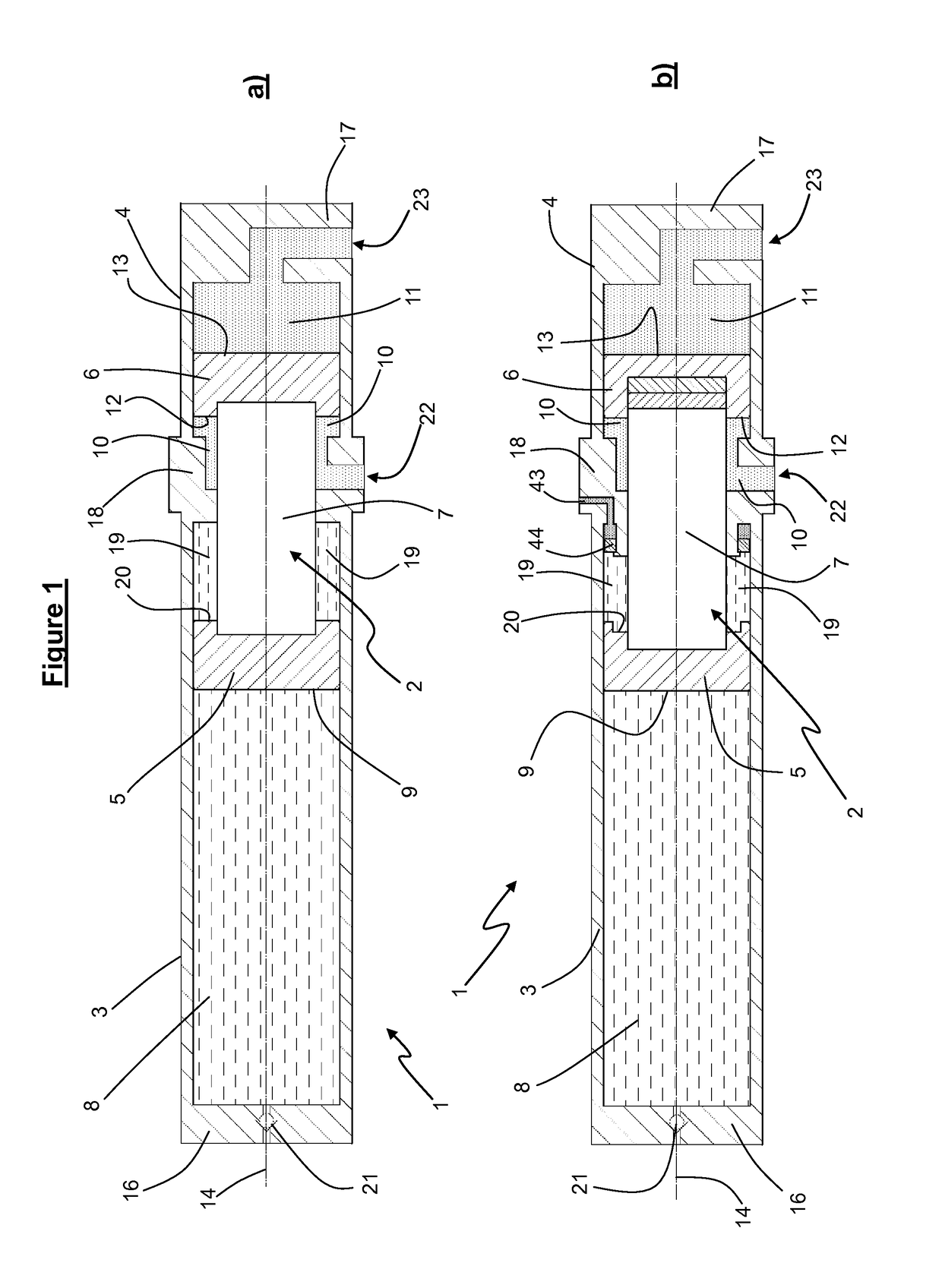
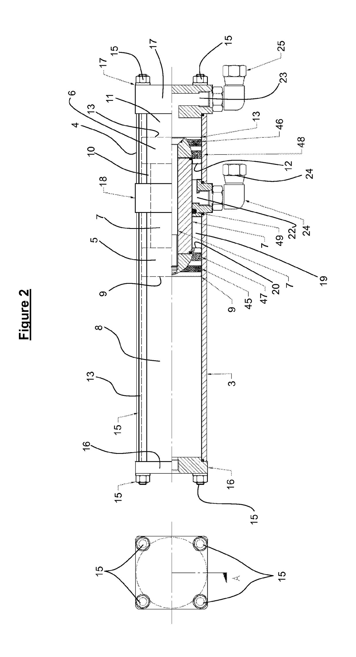
Reference numerals for FIGS. 1-10.(1) accumulator(2) piston assembly(3) first piston sleeve(4) second piston sleeve(5) first piston(6) second piston(7) connector(8) first fluid chamber(9) first piston face(10) second fluid chamber(11) third fluid chamber(12) second piston face(13) third piston face(14) longitudinal axis(15) longitudinal bolts(16) endplate(17) endplate(18) intermediary partition(19) fourth fluid chamber(20) fourth piston face(21) valved port(22) second fluid chamber port(23) third fluid chamber port(24) hydraulic connectors(25) hydraulic connectors(26) prime mover(27) hammer assembly(28) hammer weight(29) housing(30) lifting surface projection(31) drive down surface projection(32) a drive projection(33) endless drive chain(34) upper sprocket(35) lower sprocket(36) hydraulic drive motor(37) pressure line from prime mover (26) to drive motor (36)(38) pressure line from prime mover (26) to accumulator second fluidchamber(10)(39) pressure line from prime mover (26)...


PUM


Abstract

A hydraulic accumulator including an energy storage apparatus with a first piston face configured to reversibly compress an energy storage medium and a second piston face forming at least part of an inner surface of a corresponding second fluid chamber reversibly expandable by movement of the second piston face. A third piston face forms at least part of an inner surface of a corresponding third fluid chamber reversibly expandable by the third piston face. The first, second and third piston faces are coupled together.

Description

CROSS-REFERENCE TO OTHER APPLICATIONS[0001]This is a National Phase of International Application No. PCT / IB2012 / 055464, filed on Oct. 10, 2012, which claims priority from New Zealand Patent Application No. 595683, filed on Oct. 10, 2011.TECHNICAL FIELD[0002]The present invention relates to an accumulator for use in machinery and devices executing cyclic or reciprocating actions, and in particular, hydraulic, pneumatic and equivalent or related accumulators.BACKGROUND ART[0003]Accumulators are well known apparatus used in a variety of engineering fields as a means by which energy can be stored and are sometimes used to convert a small continuous power source into a short surge of energy or vice versa. Accumulators may be electrical, fluidic or mechanical and may take the form of a rechargeable battery or a hydraulic accumulator, capacitor, compulsator, steam accumulator, wave energy machine, pumped-storage hydroelectric plant or the like.[0004]Hydraulic accumulators are produced in n...

Claims


Application Information

Patent Timeline
Patent Type & Authority Patents(United States)
IPC IPC(8): F15B1/24F15B1/02E02F3/96E02D7/14E02D7/10B25D9/14E02F5/32B30B15/16B30B9/30E21B33/035F15B1/027
CPCF15B1/24B25D9/145B30B9/3057B30B15/163E02D7/10E02D7/14E02F3/966E02F5/323F15B1/024B25D2209/002E21B33/0355F15B1/027F15B2201/205F15B2201/21F15B2201/31F15B2201/32Y02E60/15F15B1/04F15B21/00Y02E60/16
Inventor ROBSON, ANGUS PETER
Owner ROBSON ANGUS PETER
Why Eureka
Try Eureka