Method and apparatus for changing the electrode tip of a TIG welder

a technology of electrode tip and tig welder, which is applied in the direction of gripping heads, metal-working machine components, manufacturing tools, etc., can solve the problems of equipment downtime and safety problems, and achieve the effects of reducing downtime, increasing safety, and reducing the use of tig welders

Active Publication Date: 2017-10-24
CHANGER & DRESSER
View PDF21 Cites 0 Cited by
  • Summary
  • Abstract
  • Description
  • Claims
  • Application Information

AI Technical Summary

Benefits of technology

[0013]The present invention provides an apparatus and method for removing used electrode tips from a TIG welder and replacing the used electrode tip with a new electrode tip. The apparatus and method provide a system that allows for greater reliability, reduces downtime and increases safety in the use a TIG welder.

Problems solved by technology

To date, this tip replacement has been a manual process which results in equipment downtime and safety issues during the replacement of the tip of the electrode being held by a robotic arm.

Method used


Image

  • Method and apparatus for changing the electrode tip of a TIG welder
  • Method and apparatus for changing the electrode tip of a TIG welder
  • Method and apparatus for changing the electrode tip of a TIG welder

Examples


Embodiment Construction

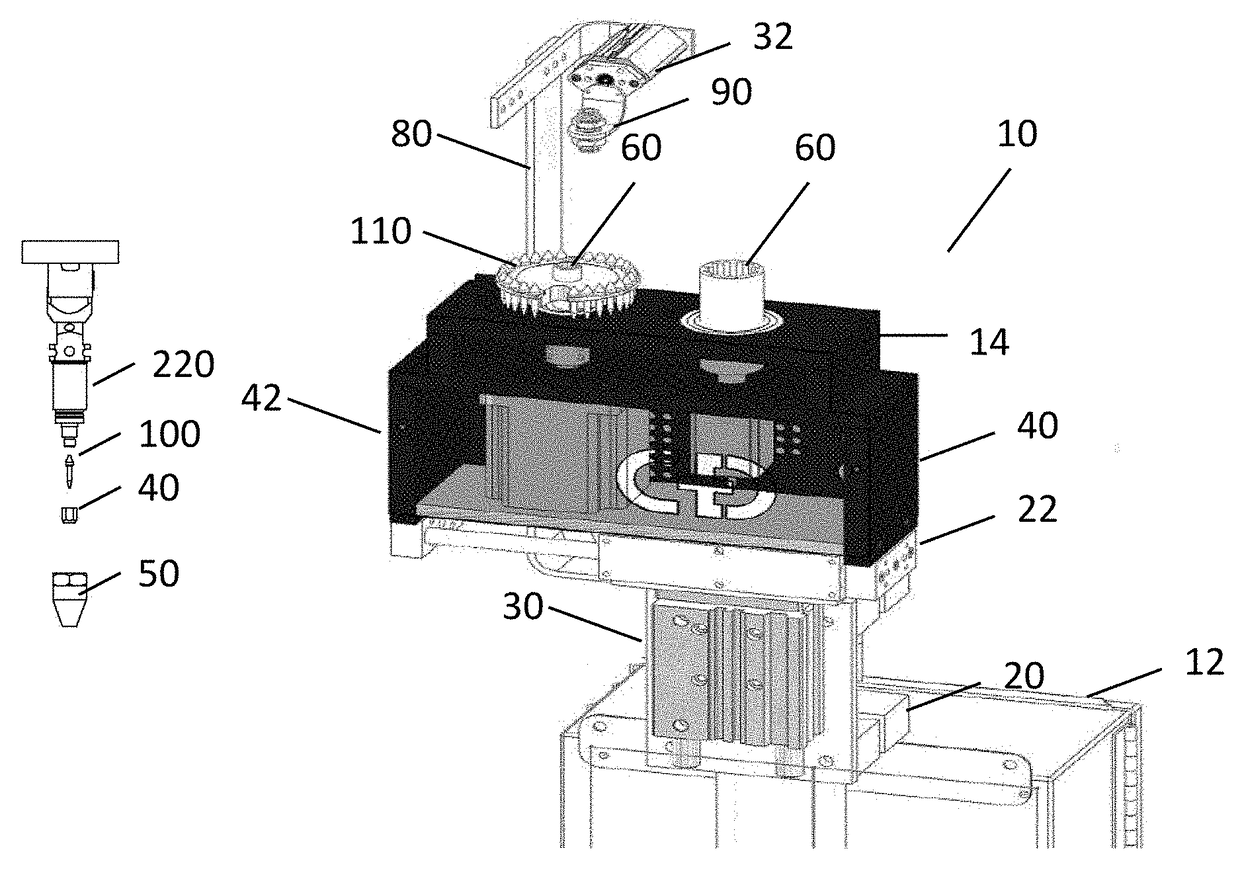
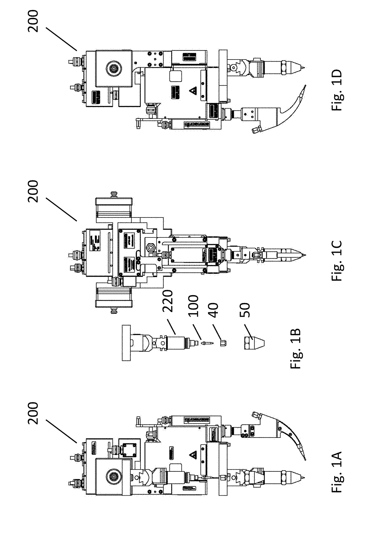
[0031]The present invention provides an apparatus and method for replacing a used electrode tip of a TIG welder with a new electrode tip. A typical TIG welder assembly 200 has a robotic arm holding the TIG welder 220 as shown in FIGS. 1A to 1D. The robotic arm must be moved to a tip change position. The tip change position places the electrode tip over the present invention. Usually, a software routine can be initiated to move the robotic arm to the tip change position.

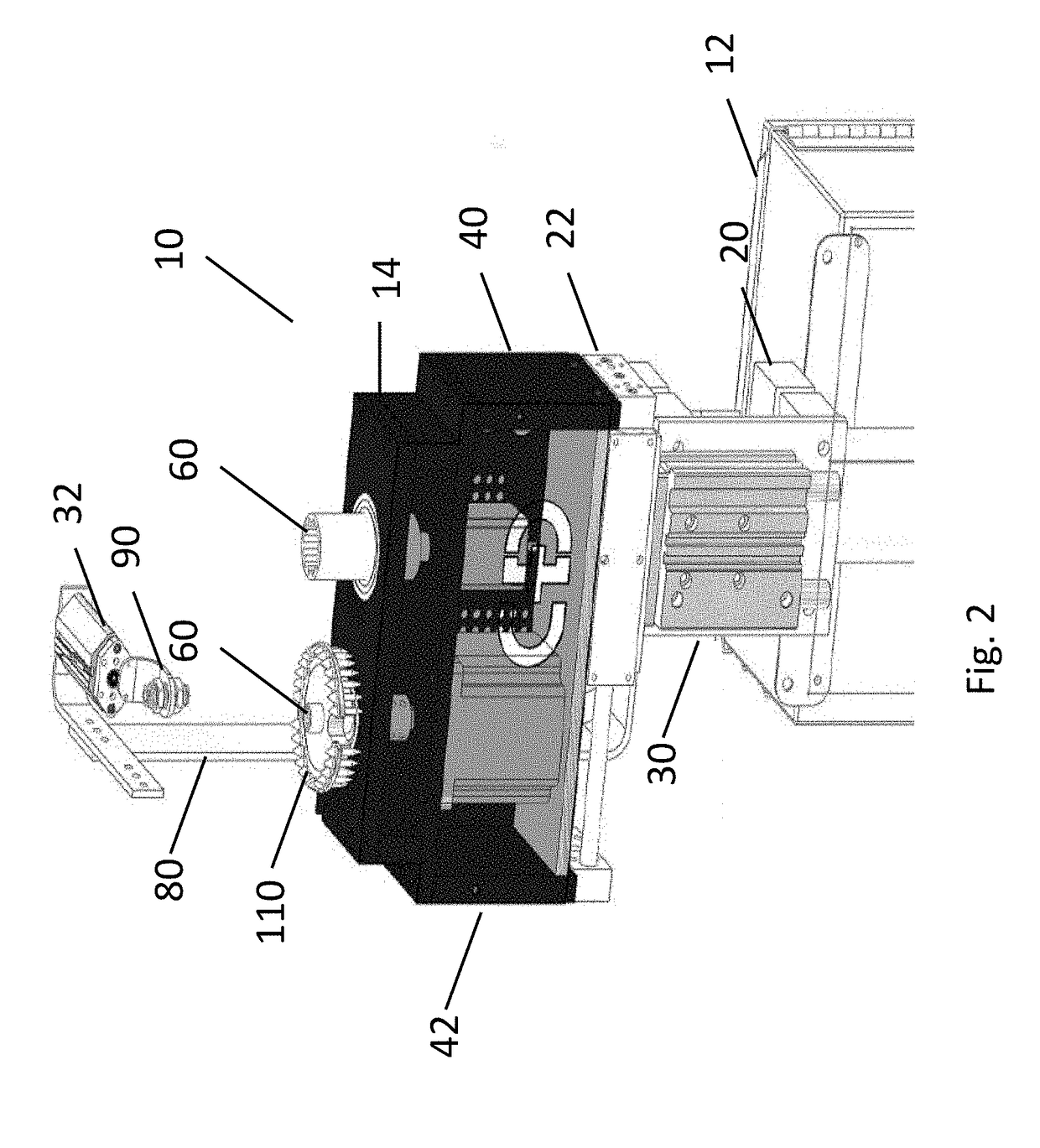
[0032]As shown in FIG. 2, the present invention 10 is an apparatus that has a lower housing structure 12 and an upper housing structure 14. The housing structures 12, 14 have a plurality of slides 20, 22 and cylinders 30, 32 (that can move up / down, left / right and rotationally, typically through a software routine) to move a first motor 40 to a first position to engage a gas shield 50 of the TIG welder 220 with a first socket adapter assembly 60.

[0033]Once the plurality of slides 20, 22 and cylinders 30, 32 start to mo...


PUM

PropertyMeasurementUnit
torqueaaaaaaaaaa
torqueaaaaaaaaaa
timeaaaaaaaaaa

Abstract

The present invention is an apparatus and method for replacing used electrode tips of a TIG welder. The apparatus has a main housing structure with a socket adapter assembly that is operatively supported by the main housing structure. The socket adapter assembly is used to both remove and re-attach the gas shield and the electrode nut of the TIG welder. A vacuum tip suction device that is operatively supported by the main housing structure is used to both remove and install electrode tips for the TIG welder.

Description

CROSS REFERENCES TO RELATED APPLICATIONS[0001]This application claims priority from and is related to commonly owned U.S. Provisional Patent Application Ser. No. 62 / 025,672 filed Jul. 17, 2014, entitled: Method and Apparatus for Changing the Electrode Tip of a TIG Welder, this Provisional Patent Application incorporated by reference herein.FIELD OF THE INVENTION[0002]The invention relates generally to welding devices, and more particularly to tools for the removal and / or installation of electrode tips into or from TIG welders.BACKGROUND[0003]The present invention relates to welding apparatus and methods used in tungsten-inert-gas (TIG) welding of steel-based materials.[0004]Conventionally, structures made of steel-based materials, such as carbon steel or stainless steel as the base material, are welded using TIG welding processes. TIG welding is widely used as a method of welding structures requiring high reliability since the welding operation can be easily performed and the welded...

Claims


Application Information

Patent Timeline
Patent Type & Authority Patents(United States)
IPC IPC(8): B23Q3/155B25J15/04B23K9/32B23K9/167B23K9/24B25J15/06
CPCB23K9/24B23K9/32B23Q3/15573B25J15/045B25J15/0616Y10T483/17B23K9/167B23K9/1675Y10T483/13
Inventor JONES, JOSHUA ERICNEWTON, DANIELL BLAKE OSCAR
Owner CHANGER & DRESSER
Why Eureka
Try Eureka