Multifunctional electrohydrodynamic inkjet printing device and printing method using the same

a multi-functional, electrohydrodynamic technology, applied in printing, printing, semiconductor devices, etc., can solve the problems of complex manufacturing process of nozzles, low resolution of jet printing, and limited droplet size, so as to improve print performance and simplify the process. , the effect of simple structur

Active Publication Date: 2017-10-24
HUAZHONG UNIV OF SCI & TECH
View PDF10 Cites 6 Cited by
  • Summary
  • Abstract
  • Description
  • Claims
  • Application Information

AI Technical Summary

Benefits of technology

[0023](3) controlling a distance between the nozzle and the rigid substrate, printing fluid flow and / or voltage applied between the nozzle and the substrate, and simultaneously controlling a movement direction and a displacement of the jet printing module with respect to the substrate bearing and moving module and / or the roll-to-roll thin film conveying module, thereby achieving jet printing of various components and / or patterns.
[0045]7. the electrohydrodynamic inkjet printing device can continuously deposit various patterns on a flexible or rigid substrate with large area.

Problems solved by technology

Conventional inkjet printing technologies have the following defects: (1) the resolution of jet printing is low, and the size of a droplet is limited by the diameter of a nozzle; (2) high viscosity solution tends to block the nozzle; (3) the manufacturing process of the nozzle is complex; (4) the printing efficiency of a large-area film and microstructure is low; and (5) the printing mode is single, so that it is impossible to produce a point-like structure, a line-like structure, or a film-like structure as may be needed.

Method used


Image

  • Multifunctional electrohydrodynamic inkjet printing device and printing method using the same
  • Multifunctional electrohydrodynamic inkjet printing device and printing method using the same
  • Multifunctional electrohydrodynamic inkjet printing device and printing method using the same

Examples


example 1

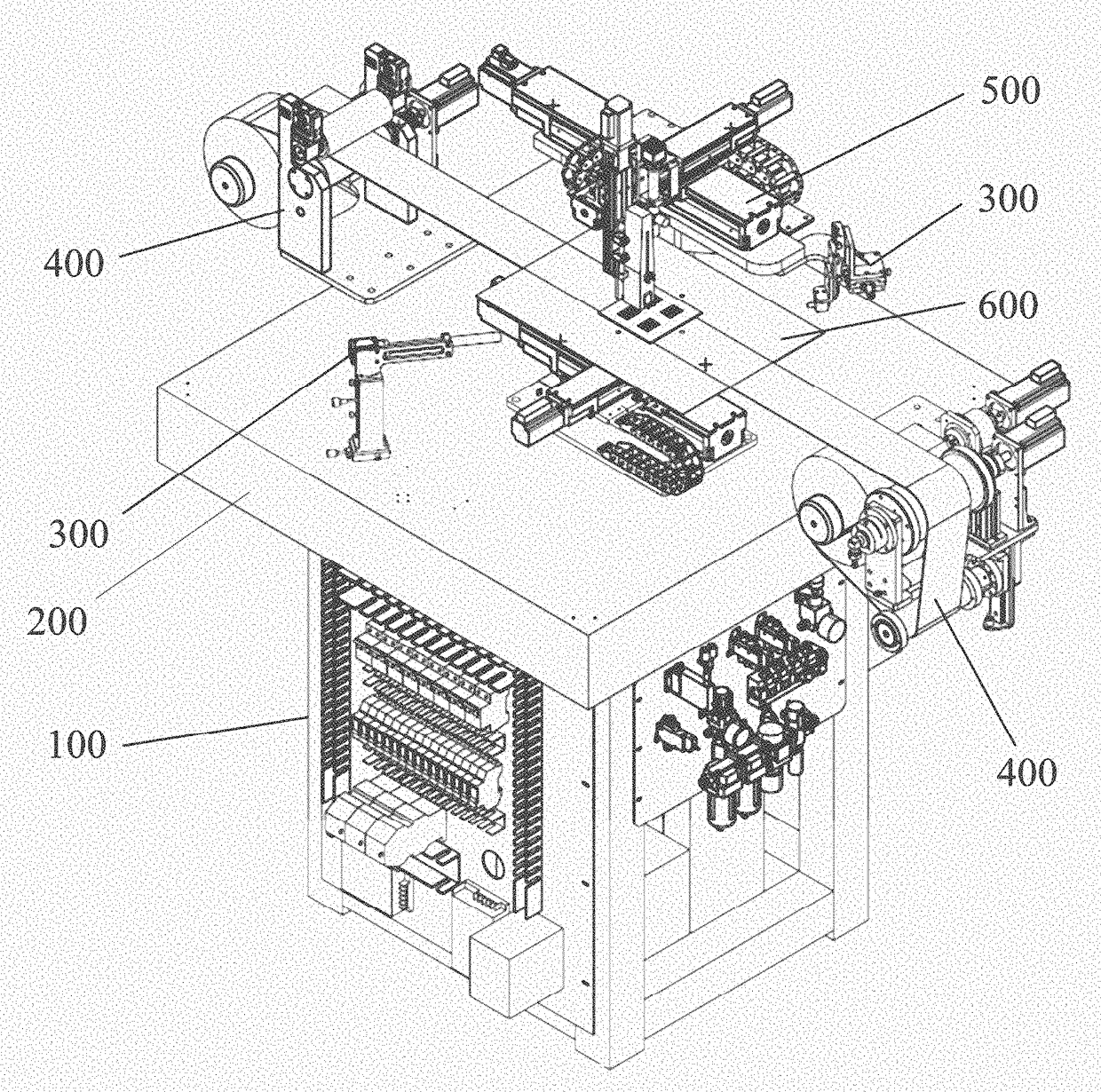
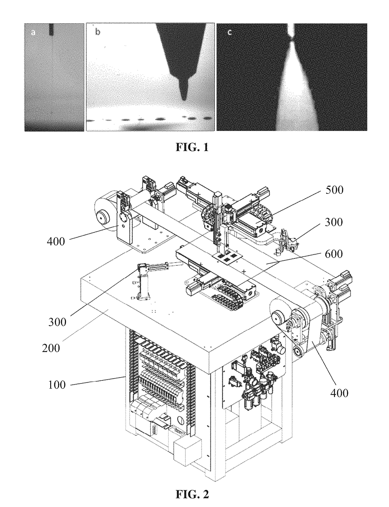
[0090]The jet printing module 500 and the substrate bearing and moving module 600 work together, and print patterns on the rigid substrate. Firstly, the substrate bearing and moving module 600 is initialized, and the X-axis motion module 602 and the Y-axis motion module 604 are adjusted so that the slider moves to the center of a motion displacement thereof. Then the rigid substrate, such as a silicon wafer, is placed at the center of the adsorption platform, and the vacuum pump is enabled by a control module, at this time negative pressure is formed at the surface of the vacuum adsorption platform, and the substrate is tightly absorbed on the adsorption platform. After that, movement of three motion modules of the jet printing module 500 is adjusted thereby enabling the nozzle to align with an edge of the substrate, namely a zero point of the printing apparatus (a height between the nozzle and the substrate determining the jet printing mode can be freely set according to calibratio...

example 2

[0091]The roll-to-roll thin film conveying module 400 and the jet printing module 500 work together, and print patterns on the flexible substrate. In this mode, the roll-to-roll thin film conveying module 400 transfers a substrate in a single direction, and movement for printing the patterns is done by the jet printing module 500. Firstly, the material roll installed on the unwinding roller 420 of the unwinding part of the roll-to-roll thin film conveying module 400, passes through a gap between the upper roller and the lower roller of the nip roller 430, and is disposed at the top of the adsorption platform, and wounded on the winding roller of the rear winding part (the mode and movement states are illustrated in FIG. 19). Prior to printing, the rigid substrate returns to an initial position right above the adsorption platform, and remains static (this can be calibrated by experiments). Then the jet printing module 500 stops moving, and remains static during printing. A height bet...

example 3

[0094]A continuous jet printing mode is used, the jet printing module 500 and the substrate bearing and moving module 600 work together, and print patterns on a sheet-shaped substrate. Firstly, the substrate bearing and moving module 600 is initialized, and the X-axis motion module 602 and the Y-axis motion module 604 are adjusted so that the slider moves to the center of a motion displacement thereof. Then an elastic PDMS substrate is placed at the center of the adsorption platform, and the vacuum pump is enabled by a control module, at this time negative pressure is formed at the surface of the vacuum adsorption platform, and the substrate is tightly absorbed on the adsorption platform. After that, movement of three motion modules of the jet printing module 500 is adjusted thereby enabling the nozzle to align with an edge of the substrate, namely a zero point of the printing apparatus. Finally a height between the nozzle and the substrate is adjusted thereby forming jet whipping. ...


PUM


Abstract

An electrohydrodynamic inkjet printing device, including: a support part; a jet printing module; a substrate bearing and moving module; and a roll-to-roll thin film conveying module. The jet printing module is disposed on the support part and includes a nozzle for ejecting printing fluid onto a substrate for pattern printing. The substrate bearing and moving module is disposed on the support part, and fixedly bears a rigid substrate as the substrate for pattern printing, and drives the rigid substrate to move with respect to the jet printing module. The roll-to-roll thin film conveying module is disposed on the support part, and transfers a flexible thin film as the substrate for pattern printing, and drives the flexible film to move with respect to the jet printing module.

Description

CROSS-REFERENCE TO RELATED APPLICATIONS[0001]This application is a continuation-in-part of International Patent Application No. PCT / CN2014 / 075804 with an international filing date of Apr. 21, 2014, designating the United States, now pending, and further claims priority benefits to Chinese Patent Application No. 201410118287.8 filed Mar. 27, 2014. The contents of all of the aforementioned applications, including any intervening amendments thereto, are incorporated herein by reference. Inquiries from the public to applicants or assignees concerning this document or the related applications should be directed to: Matthias Scholl P.C., Attn.: Dr. Matthias Scholl Esq., 245 First Street, 18th Floor, Cambridge, Mass. 02142.BACKGROUND OF THE INVENTION[0002]Field of the Invention[0003]The invention relates to an inkjet printing system, and more particularly to a multifunctional electrohydrodynamic inkjet printing device and a printing method using the same.[0004]Description of the Related Ar...

Claims


Application Information

Patent Timeline
Patent Type & Authority Patents(United States)
IPC IPC(8): B41J2/145H01L31/0224B41J25/308B41J3/407B41J3/28B41J2/07
CPCB41J2/145B41J2/072B41J3/28B41J25/308H01L31/022425B41J3/407Y02E10/50
Inventor HUANG, YONGANYIN, ZHOUPINGBU, NINGBINCHEN, JIANKUIPAN, YANQIAODING, YAJIANGDUAN, YONGQING
Owner HUAZHONG UNIV OF SCI & TECH
Why Eureka
Try Eureka