
Method for producing object

a three-dimensional object and resin material technology, applied in the field of methods for producing objects, can solve the problems of inability to achieve desired strength and difficulty in high accuracy when producing three-dimensional objects using resin materials, and achieve the effect of improving accuracy and strength of objects

Active Publication Date: 2017-10-31
SEIKO EPSON CORP
View PDF35 Cites 5 Cited by
  • Summary
  • Abstract
  • Description
  • Claims
  • Application Information

AI Technical Summary

Benefits of technology

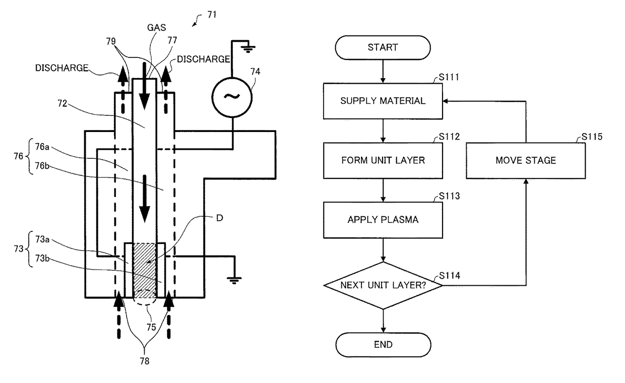
[0177]As described above, the three-dimensional modeling device 300 according to the third embodiment includes the plasma irradiation mechanism 270. The method for producing an object according to the third embodiment includes the plasma irradiation step (S133) (S133A and S133B). The above advantageous effects can be achieved by performing the discharge treatment at the timing A (S133A) or the timing B (S133B) using the plasma irradiation mechanism 270.
[0178]When the plasma irradiation step (S133A) is performed at a timing after forming the unit layer (after performing the step S134 that forms the nth layer), but before starting forming the next unit layer (before starting the step S131 that forms the (n+1)th layer), an anchor effect is achieved by moderately roughening the interface between the unit layers, and the interfacial strength (adhesion) between the unit layers is improved by forming the upper layer after breaking the polymer bonds on the surface of the unit layer. It is possible to control wettability at the interface between the unit layers, and improve the processing accuracy by selecting a gas species corresponding to the object, and performing the discharge treatment in the plasma irradiation step (S133). This makes it possible to improve the accuracy and the strength of the resulting object.
[0179]When the plasma irradiation step (S133B) is performed at a timing after performing the binder application step (S132), but before performing the energy irradiation step (S134), a thin solid film is formed on the surface of the liquid material due to radicals generated by the discharge treatment, and it is expected that a pinning effect on the liquid material is achieved. Moreover, a paste layer formed after curing the liquid material easily becomes uniform. When the binder is a radiation-curable material, inhibition of polymerization on the surface of the binder due to oxygen can be reduced by performing the discharge treatment before curing the applied binder, and the radiation-curability of the binder is improved. This makes it possible to improve the accuracy and the strength of the resulting object.1.3.4. Modifications of Third Embodiment
[0180]The three-dimensional modeling device 300 illustrated in FIG. 13 and the like is configured so that the application mechanism 250 and the energy irradiation mechanism 252 are integrated. Note that the application mechanism 250 and the energy irradiation mechanism 252 may be provided independently of each other. The application mechanism 250, the energy irradiation mechanism 252, and the plasma irradiation mechanism 270 may be integrated. The three-dimensional modeling device illustrated in FIG. 19 is configured so that the application mechanism 250A, the energy irradiation mechanism 252A, and the plasma irradiation mechanism 270 are provided independently of each other. Note that the application mechanism 250 and the plasma irradiation mechanism 270 may be integrated, or the plasma irradiation mechanism 270 and the energy irradiation mechanism 252 may be integrated, or the application mechanism 250, the energy irradiation mechanism 252, and the plasma irradiation mechanism 270 may be integrated. The head that implements these mechanisms may be a line scan head that moves in the X-direction or the Y-direction, or a serial scan head that moves in the X-direction and the Y-direction.1.4. Fourth Embodiment
[0181]The fourth embodiment illustrates a method for producing an object that utilizes a paste method. The term “paste method” refers to a method that repeats a step that supplies a paste prepared by mixing a powdered base material (main material for forming an object) with an amphiphilic solid polymer or the like in order to prevent a situation in which the base material scatters, partially applies a liquid material (binder) that binds the base material included in the paste, and cures the liquid material by applying energy to produce an object. The paste includes a resin material. The binder is a resin material. The raw material used in connection with the fourth embodiment, the configuration of the three-dimensional modeling device, and the method for producing an object according to the fourth embodiment are described below.1.4.1. Raw Material
[0182]A known material may be used as the powdered base material. For example, organic particles such as an acrylic resin powder, a silicone resin powder, an acrylic-silicone resin powder, a polyethylene resin powder, a polyethylene-acrylic acid copolymer resin powder, or starch, or inorganic particles such as gypsum, ceramic, metal, or silica may be used. These organic particles and inorganic particles may be completely spherical or porous.

Problems solved by technology

However, since a resin material having fluidity may spread during production, or may flow in an unintended direction, it has been difficult to achieve high accuracy when producing a three-dimensional object using a resin material.
If the adhesion between the unit layers is low, delamination may occur, and the desired strength may not be obtained.

Method used


Image

  • Method for producing object
  • Method for producing object
  • Method for producing object

Examples


application example 1

[0041]According to one embodiment of the invention, a method for producing an object includes forming and laying N unit layers into which an object is divided, sequentially from a first layer to an Nth layer, using a resin material as a material, or using a resin material for implementing a step, to form the object, the method including:[0042]performing a discharge treatment at either or both of a timing while forming a unit layer among the N unit layers, and a timing after forming the unit layer, but before starting forming a next unit layer among the N unit layers.

[0043]According to Application Example 1, it is possible to improve the affinity between the resin materials, or the affinity of the resin material to another material, adjust the state of the interface between the unit layers, or improve the bondability or the reactivity of the resin material, by changing the state or the properties of the interface between the unit layers using the discharge treatment. This makes it po...

application example 2

[0044]In the method for producing an object as defined in Application Example 1, the resin material may be a thermoplastic resin that melts due to heating, and the method may include supplying the resin material that has been melted to a stage, and curing the resin material to form the unit layer.

[0045]According to Application Example 2, an anchor effect is achieved by moderately roughening the interface between the unit layers using the discharge treatment, and the interfacial strength (adhesion) between the unit layers is improved by forming the upper layer after breaking the polymer bonds on the surface of the unit layer. It is possible to control wettability (degree of wetting) at the interface between the unit layers, and improve the processing accuracy by selecting a gas species corresponding to the object, and performing the discharge treatment.

application example 3

[0046]In the method for producing an object as defined in Application Example 1,[0047]the resin material may be a powdered resin material, and[0048]the method may include:[0049]supplying the powdered resin material to a stage, and partially curing the powdered resin material to form the unit layer; and[0050]performing the discharge treatment after forming the unit layer, but before starting forming the next unit layer.

[0051]According to Application Example 3, an anchor effect is achieved by moderately roughening the interface between the unit layers using the discharge treatment, and the interfacial strength (adhesion) between the unit layers is improved by forming the upper layer after breaking the polymer bonds on the surface of the unit layer.


PUM

PropertyMeasurementUnit
distanceaaaaaaaaaa
frequencyaaaaaaaaaa
volume average particle sizeaaaaaaaaaa

Abstract

A method for producing an object includes forming and laying N unit layers into which an object is divided, sequentially from a first layer to an Nth layer, using a resin material as a material, or using a resin material for implementing a step, to form the object, the method including performing a discharge treatment at either or both of a timing while forming a unit layer among the N unit layers, and a timing after forming the unit layer, but before starting forming a next unit layer among the N unit layers.

Description

[0001]Japanese Patent Application No. 2014-065667, filed on Mar. 27, 2014, is hereby incorporated by reference in its entirety.BACKGROUND OF THE INVENTION[0002]The present invention relates to a method for producing an object.[0003]In recent years, there has been an increasing demand for a 3D printer that can produce (model) a three-dimensional object. Such a 3D printer normally implements additive manufacturing. The term “additive manufacturing” refers to a method that forms and lays N unit layers into which the object is divided, sequentially from the first layer to the Nth layer.[0004]Various methods for implementing additive manufacturing have been studied, and some of them have been put to practical use. These methods may utilize a resin material as a material, or utilize a resin material for implementing a step. Specific examples of additive manufacturing that utilizes a resin material include the following methods.[0005]JP-T-2010-521339 and Japanese Patent No. 4107686 disclos...

Claims


Application Information

Patent Timeline
Patent Type & Authority Patents(United States)
IPC IPC(8): B29C59/14B29C67/00B33Y99/00B29C37/00B29C65/00B33Y10/00B33Y40/00B29K101/12B29K105/00
CPCB29C64/295B29C37/0078B29C66/028B33Y10/00B33Y99/00B29C64/264B29C64/153B29C64/165B29C64/321B29C64/20B29K2101/12B33Y40/00B29K2105/251B29C64/112B29C64/135B29C64/129B29C64/118B29C64/371B33Y40/20
Inventor DENDA, ATSUSHIKITADA, KENJINARIAI, MAKI
Owner SEIKO EPSON CORP
Learn More