Method for tire tread depth modeling and image annotation

a tire and depth modeling technology, applied in vehicle tyre testing, static indicating devices, instruments, etc., can solve the problems of excessive fuel consumption of the vehicle, dangerously susceptible to hydroplaning and loss of control, uneven tread wear across the width of the outer surface of the tire, etc., to achieve the effect of quick identification

Active Publication Date: 2017-10-31
HUNTER ENG
View PDF62 Cites 50 Cited by
  • Summary
  • Abstract
  • Description
  • Claims
  • Application Information

AI Technical Summary

Benefits of technology

[0015]The present application sets forth a vehicle service system having a means for acquiring images of a three-dimensional region of a vehicle wheel assembly tire tread surface, and which is configured to process the acquired images to produce a collection of data points corresponding to the spatial position of points in the region on the surface of the tire tread, from which tire tread wear characteristics over the region, including tread

Problems solved by technology

It is well known that the condition of the tires of a motor vehicle, and in particular, the condition of the tire tread, can have a significant impact on the performance of the vehicle as well as be indicative of potential problems with the vehicle.
For example, tires with excessive tread wear lack the ability to evacuate water from the contact patch region when traveling over wet road surfaces, leaving the vehicle dangerously susceptible to hydroplaning and a loss of control.
Uneven tread wear across the width of a tire's outer surface may be indicative of an improper wheel alignment or a broken component in the vehicle suspension system.
Improper inflation of a tire can result in the failure of the tire to properly support the vehicle, leading to bulges in the tire sidewall adjacent to the contact patch, and excessive fuel consumption by the vehicle.
However, the design of the '995 system limits the measurement of profile depth and type to a very small sliver of the tire, which is visible for the brief moment when the tire passes directly over the embedded sensor.
While many of the known systems for measuring tire tread depth employ optical sc

Method used


Image

  • Method for tire tread depth modeling and image annotation
  • Method for tire tread depth modeling and image annotation
  • Method for tire tread depth modeling and image annotation

Examples


Embodiment Construction

[0039]The following detailed description illustrates the invention by way of example and not by way of limitation. The description enables one skilled in the art to make and use the present disclosure, and describes several embodiments, adaptations, variations, alternatives, and uses of the present disclosure, including what is presently believed to be the best mode of carrying out the present disclosure.

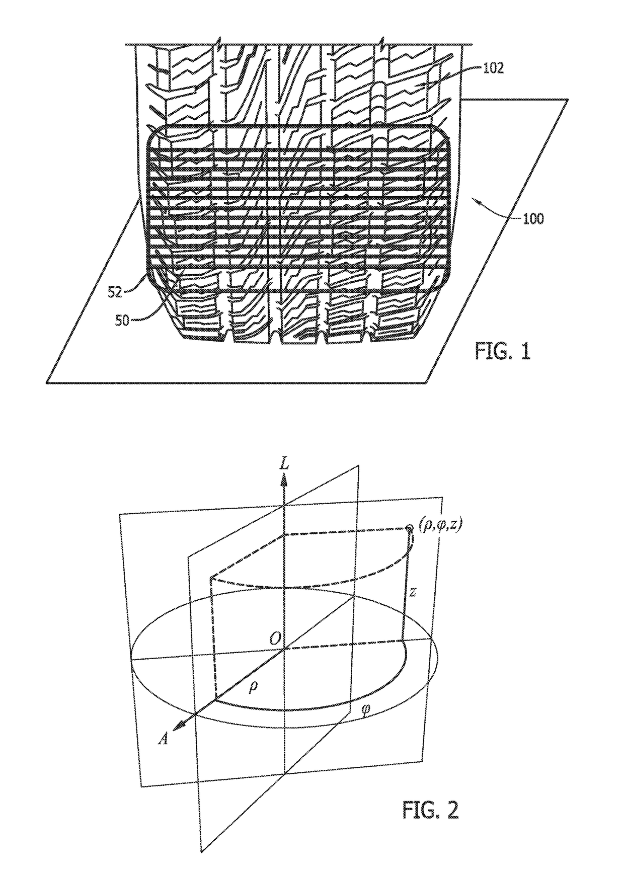
[0040]As used herein, the phrase “vehicle wheel assembly” is used generally to refer to an assembly consisting of a tire mounted to a vehicle wheel rim, however, it will be understood that the phrase is not limited there to, and is considered to include simply an unmounted tire without a vehicle rim.

[0041]Data acquired through machine vision imaging sensors used by vehicle service systems and vehicle inspection systems can be utilized in a variety of ways, including the development of a virtual model of an object being imaged, such as a vehicle wheel assembly, from a collection of d...


PUM


Abstract

A vehicle service system having a means for acquiring images of a three-dimensional region of a vehicle wheel assembly tire tread surface. The vehicle service system is configured to process the acquired images to produce a collection of data points corresponding to the spatial position of surface points in the region from which tire tread wear characteristics are identified. The acquired images are further utilized to provide both a graphical and a numerical display to an operator, with the numerical display linked to specifically annotated or indexed points or windows within the graphical display, thereby enabling an operator to quickly identify specific focus points or regions on the tire surface which have been measured at the numerically identified tread depths.

Description

CROSS-REFERENCE TO RELATED APPLICATIONS[0001]The present application is related to, and claims priority from, both U.S. Provisional Patent Application Ser. No. 61 / 654,216 filed on Jun. 1, 2012 and U.S. Provisional Patent Application Ser. No. 61 / 759,240 filed on Jan. 31, 2013, each of which is herein incorporated by reference.STATEMENT REGARDING FEDERALLY SPONSORED RESEARCH[0002]Not Applicable.BACKGROUND OF THE INVENTION[0003]The present invention relates generally to machine vision vehicle service systems configured to measure parameters associated with one or more wheel assemblies on a vehicle, and more particularly, to a vehicle service system and methods for acquiring and processing image data representative of a three-dimensional region of a tire tread surfaces associated a vehicle wheel assembly to provide an operator with information related to the condition of the tire tread.[0004]It is well known that the condition of the tires of a motor vehicle, and in particular, the cond...

Claims


Application Information

Patent Timeline
IPC IPC(8): G01M17/02H04N13/02G09G5/40G01B21/18G01N21/95B60C99/00G01B11/22G06V10/44
CPCG09G5/40B60C99/006H04N13/0203G09G5/14G09G2340/12G09G2380/10G06V20/647G06V10/44H04N13/204
Inventor DORRANCE, DANIEL R.COLARELLI, III, NICHOLAS J.STREGE, TIMOTHY A.
Owner HUNTER ENG
Why Eureka
Try Eureka