Device for monitoring a power transmission system of an aircraft, an aircraft provided with the device, and the method used

a technology for aircraft power transmission and aircraft, which is applied in the direction of gas turbine engine testing, jet-propulsion engine testing, transportation and packaging, etc., can solve the problems of insufficient maximum authorized power for the engine, insufficient power for the maximum authorized engine, and the assumption of consumption can turn out to be rather inaccurate, so as to maintain the level of aircraft performance

Active Publication Date: 2017-11-14
EUROCOPTER
View PDF12 Cites 2 Cited by
  • Summary
  • Abstract
  • Description
  • Claims
  • Application Information

AI Technical Summary

Benefits of technology

[0075]The results of the testing stage make it possible to prepare the power relationship that gives a first power parameter reduced by the relative density of the air.
[0084]Specifically, the aircraft may include a management member for each engine, such as for example a full authority digital engine control (FADEC). By way of example, the management member may control the rate at which fuel is delivered to the engine so that the power developed by each engine does not exceed high and / or low limits, at least while the engine is operating in certain power ratings.
[0085]These power bounds seek to guarantee that the aircraft is pilotable when a pilot acts on the collective pitch of the blades of the main rotor. These bounds can also guarantee mechanical integrity of the power transmission system and they can maintain a level of performance for the aircraft in the event of a malfunction of the device applying the invention, e.g. a malfunction of the system that measures the current position of the control means.
[0105]For example, the management member of each engine may control the rate at which fuel is delivered to the engine so that said current torque does not exceed the limit torque, at least while the engine is operating at certain power ratings.
[0108]This first implementation makes it possible to obtain a power relationship that is relatively accurate.

Problems solved by technology

Furthermore, in order to guarantee mechanical integrity of the power plant, three engine-monitoring parameters are conventionally defined and limited, namely: the temperature known as “T4” of the gas in the combustion chamber of each engine; the speed of rotation Ng of the gas generator in each engine; and the torque Tq exerted on a drive shaft of each engine that is connected to the main gearbox.
In addition, a manufacturer applies limits in order to protect the inlet of the main gearbox, the rotor mast, and the auxiliary unit from excessive torque.
In addition, for reasons of cost and of difficulty in implementing a torque meter, it is only the engines that are generally provided with such torque meters.
Nevertheless, for the mechanical limits of the power transmission system, the gearbox inlet torque limit is thus established on the basis of an “assumed” level of power being consumed by the auxiliary unit.
This assumed consumption can turn out to be rather inaccurate, for example when performing a sideways movement during hovering flight or in the presence of a gust of cross wind.
Under such circumstances, the maximum authorized power for the engines is not sufficient to obtain the maximum authorized power in the rotor mast as used in that power relationship.
This situation leads to an arbitrarily restrictive limit on the performance of the aircraft under difficult flight circumstances.

Method used


Image

  • Device for monitoring a power transmission system of an aircraft, an aircraft provided with the device, and the method used
  • Device for monitoring a power transmission system of an aircraft, an aircraft provided with the device, and the method used
  • Device for monitoring a power transmission system of an aircraft, an aircraft provided with the device, and the method used

Examples


Embodiment Construction

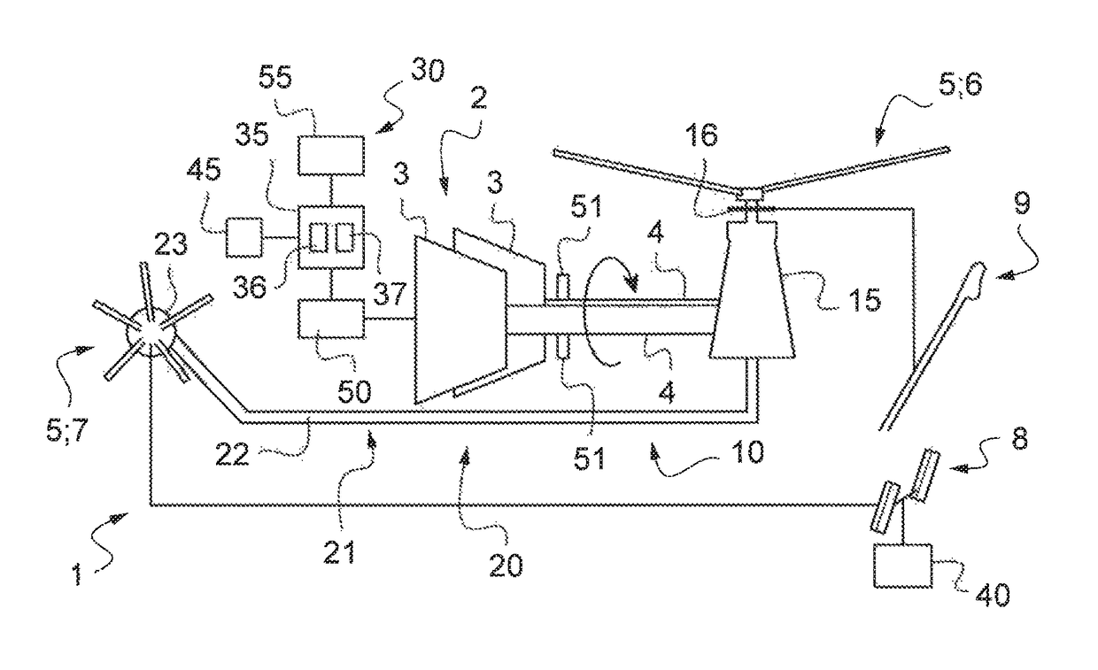
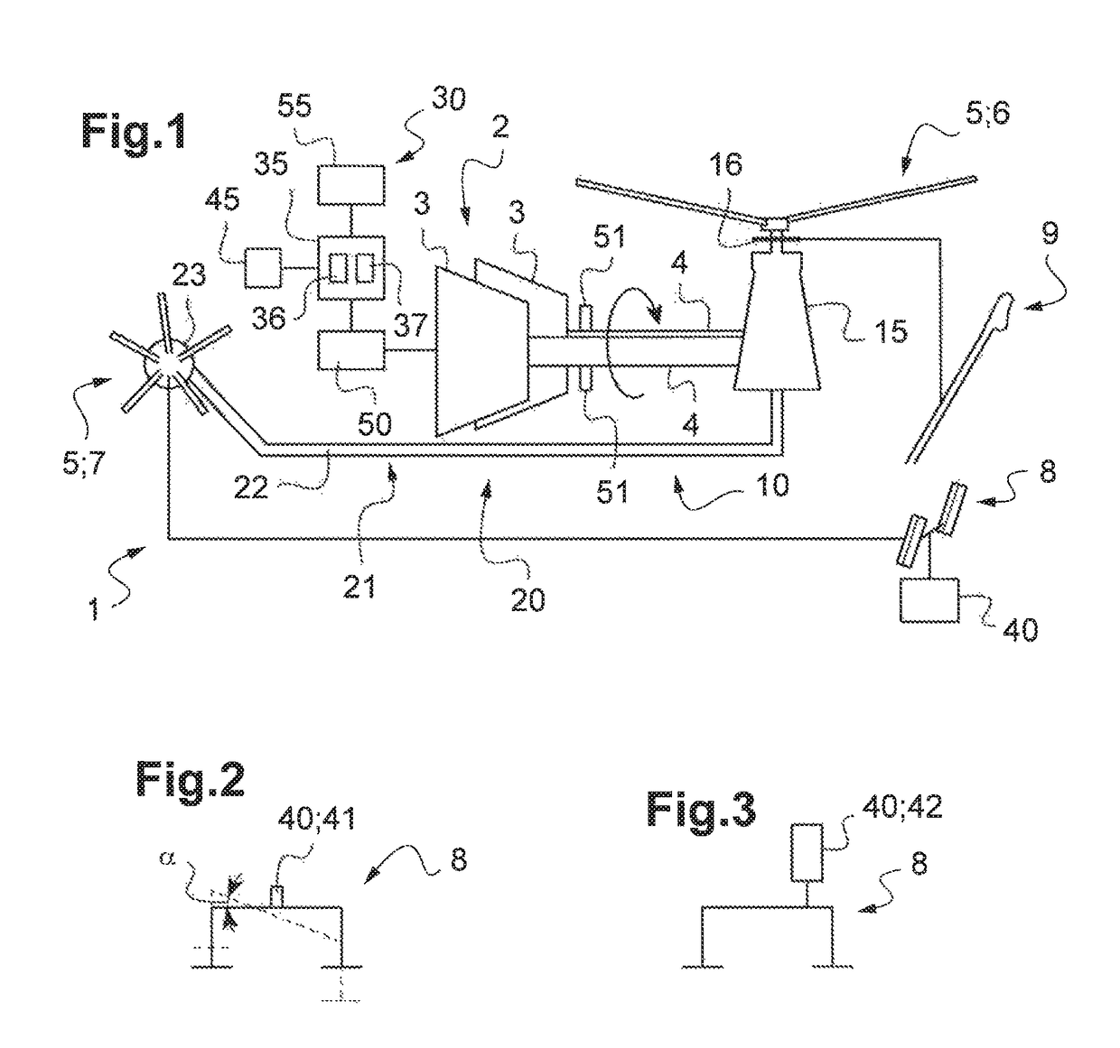
[0135]FIG. 1 shows an aircraft 1 of the invention.

[0136]The aircraft 1 has at least two rotors 5. In particular, the aircraft 1 shown diagrammatically has a main rotor 6 providing the aircraft 1 with at least some of its lift and propulsion. The aircraft 1 also has an auxiliary unit 20 with an auxiliary rotor for controlling yaw movement of the aircraft 1. Consequently, the aircraft 1 in FIG. 1 is a rotorcraft, and more precisely a helicopter.

[0137]In order to control this aircraft, a pilot operates flight controls.

[0138]Thus, the aircraft 1 has controls 9 for controlling the pitch of the blades of the main rotor cyclically and / or collectively. Consequently, and by way of example, these controls 9 may include a cyclic stick and a collective lever respectively for controlling the cyclic pitch and the collective pitch of the blades of the main rotor 6.

[0139]Furthermore, the aircraft 1 has control means 8 for controlling the pitch of the blades of the auxiliary rotor 7. Such control me...


PUM


Abstract

A method of monitoring a power transmission system of an aircraft, the aircraft including at least one main rotor driven in rotation by a rotor mast and an auxiliary unit having an auxiliary rotor. Control means control the auxiliary rotor. A power relationship is determined providing a first reduced power parameter of the auxiliary unit as a function of a position (POS) of the control means. A setpoint limit is set for a second power parameter for the rotor mast. A current position (POSACTU) of the control means is determined and a calculated value (Vcal) is also determined at least by applying the current position (POSACTU) to the power relationship. A limit value that is not to be exceeded by a power plant is determined, with the limit value being equal to the sum at least of the setpoint limit plus the calculated value.

Description

CROSS REFERENCE TO RELATED APPLICATION[0001]This application claims priority to French patent application No. FR 15 00166 filed on Jan. 29, 2015, the disclosure of which is incorporated in its entirety by reference herein.BACKGROUND OF THE INVENTION[0002](1) Field of the Invention[0003]The present invention relates to a monitoring device for monitoring a power transmission system of an aircraft, to an aircraft fitted with the monitoring device, and to the method used.[0004](2) Description of Related Art[0005]In particular, the aircraft is a rotorcraft having a main rotor providing the rotorcraft with at least part of its lift and possibly also propulsion. The rotorcraft also has at least one auxiliary member for controlling its movement in yaw.[0006]In particular, and by way of example, a helicopter may include both a main rotor and an auxiliary member that are driven in rotation by a power plant. Such an auxiliary member may for example be provided with a rotor that is referred to ...

Claims


Application Information

Patent Timeline
Patent Type & Authority Patents(United States)
IPC IPC(8): G01M15/14B64D45/00B64C27/12B64D31/06B64C27/08G01M13/02B64C27/82
CPCB64D45/00B64C27/08B64D31/06G01M13/02B64C27/12B64C27/82B64C27/14B64D2045/0085
Inventor VALLART, JEAN-BAPTISTETAHERI, SETAREHLEYDER, SAMUEL
Owner EUROCOPTER
Why Eureka
Try Eureka