
Methods, systems, and computer medium having computer programs stored thereon to optimize reservoir management decisions

a technology of optimization and reservoir management, applied in the direction of borehole/well accessories, analogue processes for specific applications, instruments, etc., can solve the problems of insufficient utilization of static parameters, insufficient flexibility in changing surface locations later, and high cost of well drilling, etc., to achieve more accurate results

Active Publication Date: 2017-11-14
SAUDI ARABIAN OIL CO +1
View PDF18 Cites 3 Cited by
  • Summary
  • Abstract
  • Description
  • Claims
  • Application Information

AI Technical Summary

Benefits of technology

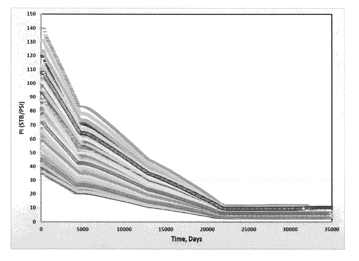
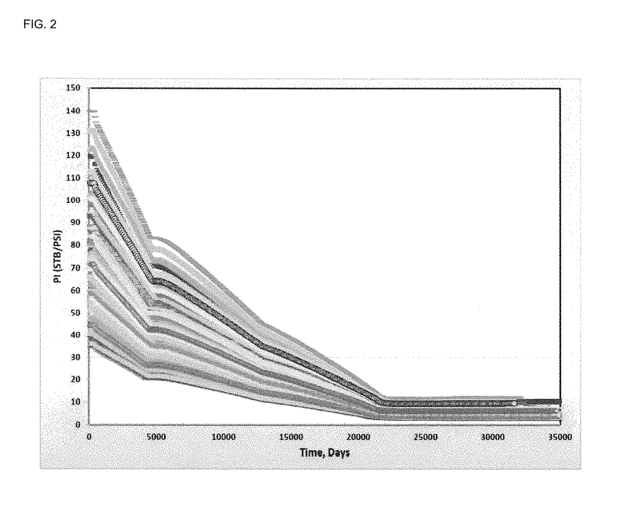
The patent discusses using static parameters to find the optimum location of wells, but it recognizes that once the field starts producing, parameters will change due to fluid flow and saturation. The industry has come to accept that dynamic maps generated from dynamic parameters provide accurate images of the quality of a reservoir rock relative to the active forces within it. In simple terms, the patent is suggesting that static parameters are not enough to find the optimum location of wells, and dynamic parameters need to be used to get a more accurate picture of the quality of the reservoir rock.

Problems solved by technology

Drilling of wells is costly, often amounting to hundreds of millions of dollars for a reservoir, depending on the number and types of wells involved.
Once wells are drilled, there is no flexibility in changing surface locations later.
Static parameter utilization, however, is not sufficient to find the optimum location of wells.
The fact that it requires long simulation runs to obtain one map, especially in large models, could cause researchers to shy away from implementing quality maps approach in real reservoirs.

Method used


Image

  • Methods, systems, and computer medium having computer programs stored thereon to optimize reservoir management decisions
  • Methods, systems, and computer medium having computer programs stored thereon to optimize reservoir management decisions
  • Methods, systems, and computer medium having computer programs stored thereon to optimize reservoir management decisions

Examples


Embodiment Construction

[0027]The present invention will now be described more fully hereinafter with reference to the accompanying drawings, which illustrate various embodiments of the invention. This invention, however, may be embodied in many different forms and should not be construed as limited to the embodiments set forth herein. Rather, these embodiments are provided so that this disclosure will be thorough and complete, and will fully convey the scope of the invention to those skilled in the art. It is to be fully recognized that the different teachings of the various embodiments discussed below may be employed separately or in any suitable combination to produce desired results. The various characteristics mentioned above, as well as other features and characteristics described in more detail below, will be readily apparent to those skilled in the art upon reading the following detailed description of the various embodiments, and by referring to the accompanying drawings. In the drawings and descr...


PUM


Abstract

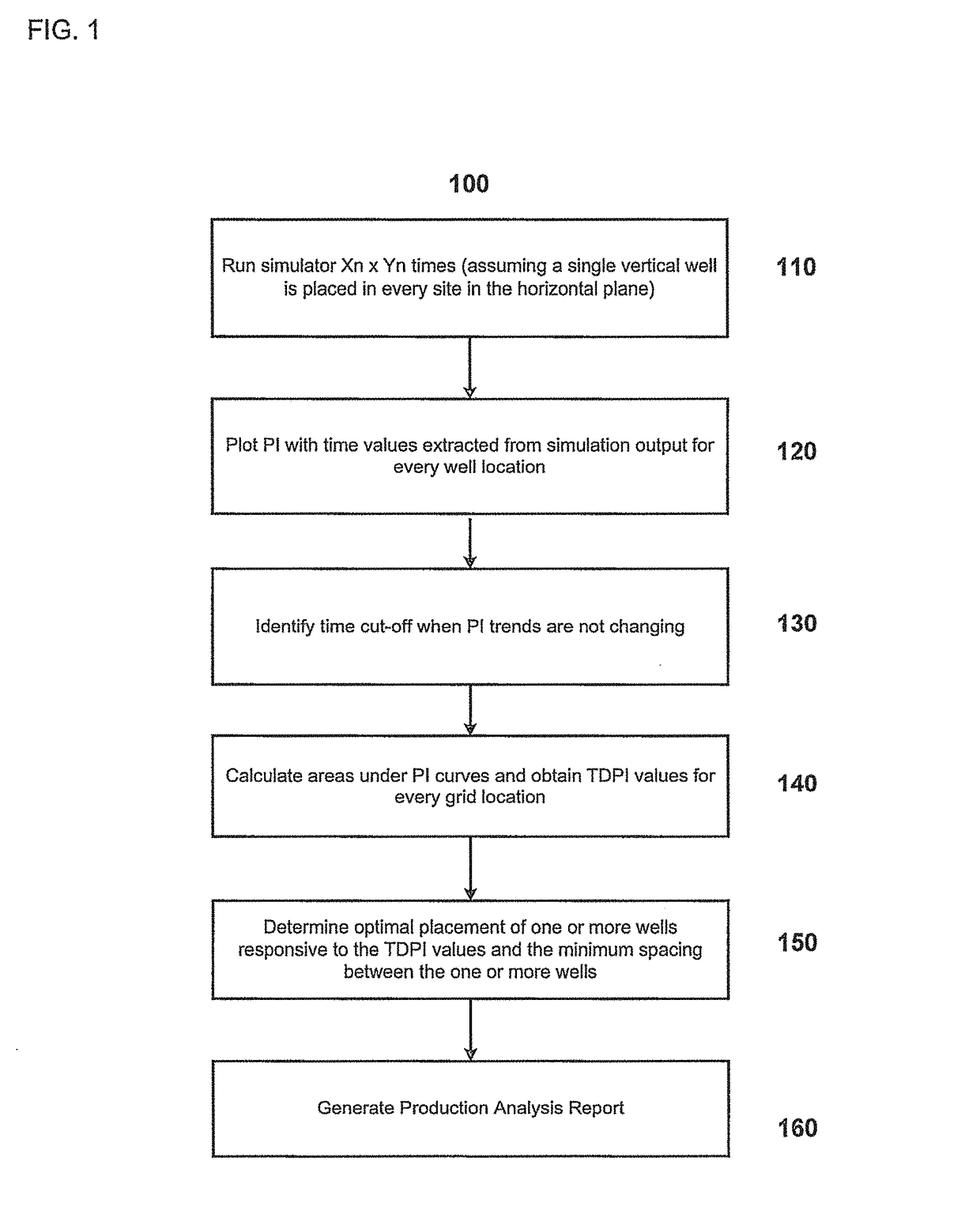
Embodiments of the invention include systems, methods, and computer-readable mediums for optimizing the placement of wells in a reservoir. Embodiments include, for example, determining for a reservoir a productivity index for each coordinate of a reservoir using reservoir metrics associated with the reservoir, generating a grid pattern of the reservoir using the productivity index with time values extracted for each coordinate, determining a total dynamic productivity index for each coordinate, and determining placement of one or more wells responsive to the total dynamic productivity index and minimum spacing between the one or more wells. Embodiments further include, for example, generating a production analysis report for the reservoir that includes an assessment of well placement and generating a wells placement map using one or more total dynamic productivity index indicators.

Description

CROSS-REFERENCE TO RELATED APPLICATIONS[0001]The present invention relates to optimizing the placement of wells in an oilfield, as does a commonly owned, co-pending U.S. Patent Application titled, “Multilateral Wells Placement via Transshipment Approach” filed Jul. 14, 2014, Ser. No. 14 / 330,510, which is incorporated herein by reference in its entirety.FIELD OF THE INVENTION[0002]This invention relates to optimizing the placement of wells in an oilfield. More specifically, this invention relates to wells placement optimization and reservoir management using total dynamic productivity index maps.BACKGROUND OF THE INVENTION[0003]Identifying the optimum production strategy for a field development plan is a critical decision to be made with reservoir management. Drilling of wells is costly, often amounting to hundreds of millions of dollars for a reservoir, depending on the number and types of wells involved. Once wells are drilled, there is no flexibility in changing surface locations ...

Claims


Application Information

Patent Timeline
Patent Type & Authority Patents(United States)
IPC IPC(8): G06G7/48G06F17/50G06Q10/04E21B43/30E21B41/00G01V99/00
CPCE21B43/30E21B41/0092G06Q10/04G06F17/5009G01V99/005E21B43/00G06F30/20E21B41/00G01V20/00
Inventor ALQAHTANI, GHAZI D.SOLIMAN, MOHAMED Y.DE FARIAS, JR., ISMAEL REGIS
Owner SAUDI ARABIAN OIL CO
Learn More