Air treatment system

a technology of air treatment system and air filter, which is applied in the direction of separation process, dispersed particle separation, chemistry apparatus and processes, etc., can solve the problems of affecting the complexity and effort required to replace the filter, requiring occasional replacement, and limited life of conventional particulate filters and carbon filters, etc., to facilitate an improved control experience, improve the control system, and improve the effect of the control experien

Active Publication Date: 2017-11-21
ACCESS BUSINESS GRP INT LLC
View PDF48 Cites 16 Cited by
  • Summary
  • Abstract
  • Description
  • Claims
  • Application Information

AI Technical Summary

Benefits of technology

[0007]The present invention provides an air treatment system having an improved control system. In one embodiment, the control system includes a “dead front” display that provides the ATS with a clean and simple appearance, and that facilitates an improved control experience. The display may include a plurality of informative display elements and a plurality of touch sensors that are selectively illuminated by an underlying arrangement of light sources, such as LEDs. To produce the desired graphics, each light source may be covered by a screen having a mask layer and a diffuser layer. A translucent cover may be disposed over the control system to hide the underlying structure and allow the graphic images to be seen only when illuminated. The translucent cover may be integrated into a removable front cover that closes the front of the ATS. In one embodiment, the electronics module includes a light duct assembly have a plurality of individual ducts joined side-by-side to shepherd light from the light sources to the corresponding display elements.
[0009]In one embodiment, the ATS has a removable front cover that overlies the display, and the control system is configured to recognize touches differently depending on whether or not the cover is installed or removed. This allows a user to control the system whether or not the cover is in place. In one embodiment, the control system is configured to enable a different set of control options depending on whether or not the cover is installed. For example, the control system may offer a reduced set of control options and / or additional control options when the cover is removed. The control system may recognize whether the cover is installed or removed using one or more of the capacitive touch sensors, such as the proximity sensor.
[0011]In another aspect, the present invention provides a front cover with a magnetic interlock that allows for easy installation and removal, as well as allowing the control system to recognize whether or not the cover is installed. In one embodiment, the front cover includes one or more mechanical attachment points at the top and one or more magnetic attachment points at the bottom. The mechanical attachment point may include a lip that is configured to catch on a corresponding structure in the ATS housing. For example, the lip may catch on the electronics module to help ensure true registration between the front cover and the electronics module. The size, shape and configuration of the catch may vary. For example, it may extend generally across the width of the front cover or it may extend across only a central portion of the front cover. As another example, the lip may be integrally formed with the front cover or may be a separate component that is attached to the front cover after manufacture. The front cover may be manufactured from a translucent plastic that is configured to provide the appearance of opacity, while allowing light from the display to shine through. In one embodiment, the exposed surface of the front cover may be covered with a film that is applied using an in-mold film process. In another embodiment, the exposed surface may be covered with a thin layer of paint using a spray process or a direct transfer process (i.e. silk screen or pad printing, or thermal film transfer). Alternatively, the front cover may be generally opaque and may include a window overlying the display. The window may be manufactured from a translucent plastic that is configured to provide the appearance of opacity, while allowing light from the display to shine through. In one embodiment, the exposed surface of the window may be covered with a film that is applied using an in-mold film process. In another embodiment, the exposed surface of the window may be covered with a thin layer of paint using a spray process or a direct transfer process (i.e. silk screen or pad printing, or thermal film transfer).
[0013]In another aspect, the present invention provides a filter retainer assembly that provides for easy and secure installation of the filters. In this embodiment, the ATS includes a particular filter and an activated carbon filter. The activated carbon filter is fitted into the filter housing first and the particulate filter is fitted into the filter housing over the carbon filter. The particulate filter is secured to the ATS housing at its periphery by one or more clips that interact with corresponding structure in the ATS. The clip or clips may be configured to perform in a cam-like manner to firmly clamp the particulate filter and carbon filter in place. The ATS may also include a prefilter that is snap-fitted onto the particulate filter. The prefilter may include a coarse filter media that is supported by a grid-like prefilter retainer.

Problems solved by technology

Air treatment systems continue to grow in popularity as concerns about air quality remain an issue of significant concern.
Conventional particulate filters and carbon filters have a limited life and require occasional replacement.
The structure of the air treatment system and the mechanisms used to secure the filters within the air treatment system can have a meaningful impact of the effectiveness of the system and can dramatically affect the complexity and amount of effort required to replace the filters.

Method used


Image

  • Air treatment system
  • Air treatment system
  • Air treatment system

Examples


Embodiment Construction

[0079]A. Overview

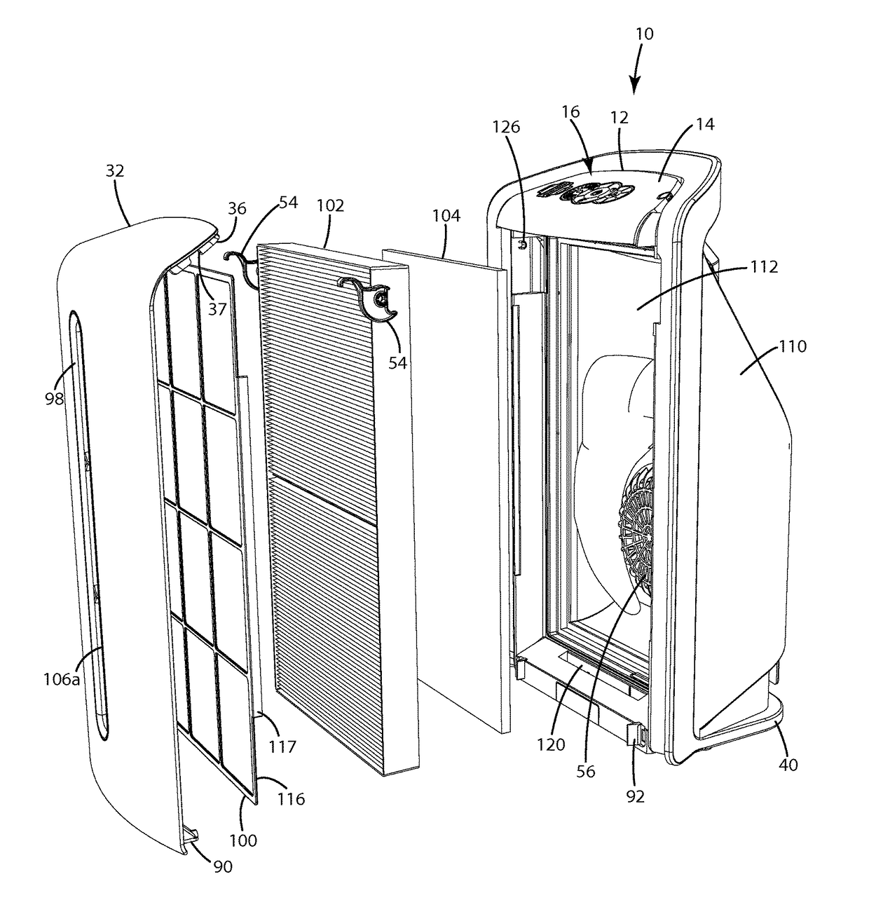
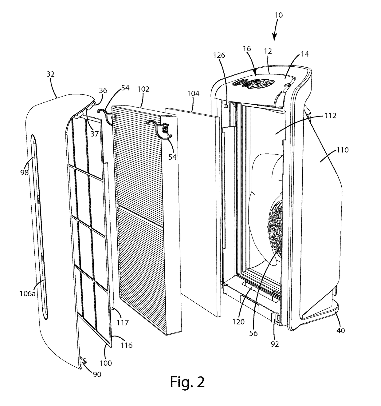
[0080]An air treatment system (“ATS”) in accordance with an embodiment of the present invention is shown in FIG. 1. The ATS 10 of the illustrated embodiment generally includes a prefilter 100, a particulate filter 102 and an activated carbon filter 104. The ATS 10 also includes a blower 56 for drawing air from the environment into the ATS 10, moving the air through the filters and returning the filtered air to the environment.

[0081]The ATS 10 of the illustrated embodiment includes a control system 12 having an electronics module 14 that provides a “dead front” display 16. The display 16 of this embodiment includes a plurality of display elements 18 that can be selectively illuminated by the control system 12 to provide dynamic content. Some of the display elements 18 may include a touch sensor 20 that allows operator input. In this embodiment, the electronics module 14 includes a plurality of light sources 22, such as LEDs, each being uniquely assigned to a display ...


PUM

PropertyMeasurementUnit
timeaaaaaaaaaa
timeaaaaaaaaaa
translucencyaaaaaaaaaa

Abstract

An air treatment system having an improved control system. The control system may include a dynamic “dead front” display that varies the display based on mode of operation. The display may include capacitive touch sensors and include an array of capacitive film segments or traces integrated into the display. The control system may include a self-contained electronics module that can be tested and calibrated before installation in the ATS. A dust sensor assembly may be integrated into the electronics module. The front cover may be attached with a mechanical attachment at the top and a magnetic attachment on the bottom. The ATS may include a filter retainer assembly with a rotating clip configured to perform in a cam-like manner to firmly clamp the particulate filter and carbon filter in place.

Description

CROSS REFERENCE TO RELATED PATENT APPLICATIONS[0001]This patent application claims benefit of 61 / 989,089 filed on May 6, 2014 and is a continuation-in-part of U.S. patent application Ser. No. 29 / 482,136 filed on Feb. 14, 2014, now Patent No. D739512, and a continuation-in-part of U.S. patent application Ser. No. 29 / 490,049 filed on May 6, 2014, now Patent No. D765234.BACKGROUND OF THE INVENTION[0002]The present invention relates to air treatment systems and more particularly to a portable room air filtering system.[0003]Air treatment systems continue to grow in popularity as concerns about air quality remain an issue of significant concern. This growth has led to an increase in the use of commercial and residential air treatment systems. A conventional residential air treatment system is a self-contained unit that can be placed in a room where it is desirable to treat the air. Residential air treatment systems generally operate by drawing room air into them, treating the air with on...

Claims


Application Information

Patent Timeline
Patent Type & Authority Patents(United States)
IPC IPC(8): B01D46/42B01D46/00
CPCB01D46/0023B01D46/4254B01D46/62
Inventor STONER, JR., WILLIAM T.LAUTZENHEISER, TERRY L.EURICH, SEAN T.NORCONK, MATTHEW J.
Owner ACCESS BUSINESS GRP INT LLC
Why Eureka
Try Eureka