Hydrokinetic torque coupling device for a motor vehicle

a technology of hydrokinetic torque and coupling device, which is applied in the direction of fluid gearing, mechanical equipment, gearing, etc., can solve the problems affecting the quality of filtration obtained using damping means, and achieve the effect of simple, efficient and cost-effectiv

Active Publication Date: 2017-11-21
VALEO EMBRAYAGES SAS
View PDF37 Cites 4 Cited by
  • Summary
  • Abstract
  • Description
  • Claims
  • Application Information

AI Technical Summary

Benefits of technology

[0011]The invention more particularly aims at providing a simple, efficient and cost-effective solution to this problem.

Problems solved by technology

The break of slope between the first and second portions of the curve may generate vibrations and a significant hysteresis upon operation of the torque converter which might affect the quality of filtration obtained using the damping means.

Method used


Image

  • Hydrokinetic torque coupling device for a motor vehicle
  • Hydrokinetic torque coupling device for a motor vehicle
  • Hydrokinetic torque coupling device for a motor vehicle

Examples


first embodiment

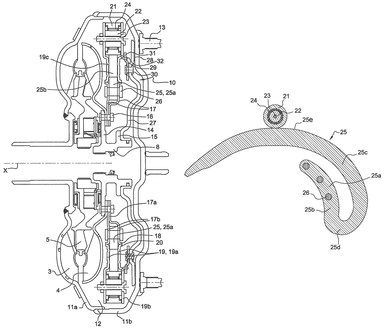
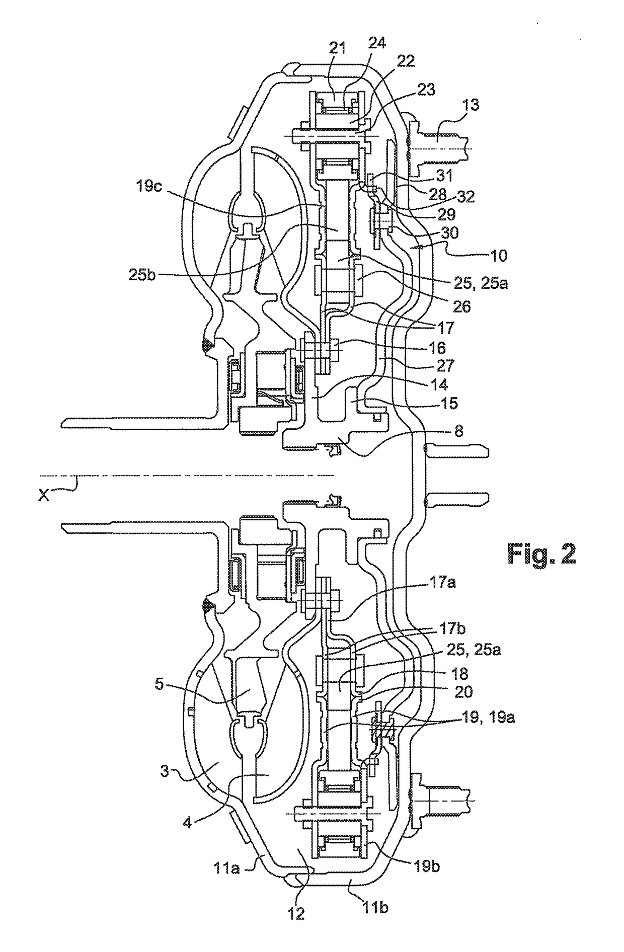
[0057]A hydrokinetic torque coupling device according to the invention is shown in FIG. 2.

[0058]The hydrokinetic torque coupling device is more particularly a hydrodynamic torque converter.

[0059]Such device makes it possible to transmit a torque from the output shaft of an internal combustion engine in a motor vehicle, such as for instance a crankshaft 1, to a transmission input shaft 2. The axis of the torque converter bears reference X.

[0060]In the following, the words “axial” and “radial” are defined relative to the X axis.

[0061]The torque converter conventionally comprises an impeller wheel 3, able to hydrokinetically drive a turbine bladed wheel 4 through a reactor 5.

[0062]The impeller wheel 3 is fastened to a cover consisting of two bell-shaped parts 11a, 11b assembled together by welding and defining an internal volume 12 accommodating the impeller wheel 3, the turbine wheel 4 and the reactor 5. Said cover 11a, 11B, also more generally referred to as cover 11, comprises faste...

second embodiment

[0094]FIGS. 5 to 8 show the invention, which is different from the one shown in FIGS. 2 to 4 in that the piston 27 is connected to one of the external flanges 19, more particularly the external flange 19 positioned close to the piston 27, through lugs 33 elastically deformable in the radial direction, so as to enable an axial motion of the piston 27 relative to the external flange 19 while providing a rotational coupling of the piston 27 and of the external flange 19. Said lugs 33 may be provided as a single piece with the external flange 19 or be formed by lugs independent of said flange 19 and fastened thereto, by rivets 34 or by welding, for instance.

[0095]The matching flange 19 may more specifically comprise lugs 35 on the radially internal periphery of said flange 19, with said lugs being formed by cutting and folding, for instance, so as to axially extend toward the piston 27.

[0096]The elastic lugs 33 are fastened to the piston 27 by rivets 30 positioned radially inside, relat...

third embodiment

[0097]FIG. 9 shows the invention, which is different from the one shown in FIG. 2 in that only one external flange 19 and one internal flange 17 are provided with cylindrical rims, with a rolling bearing, such as a ball bearing 36, being mounted between the cylindrical rims 18, 20. The external flanges 19 are thus so mounted as to pivot about the internal flanges 17, through the bearing 36.

[0098]A bearing may of course be provided between each internal flange 17 and each matching external flange 19. In this case, each flange 17, 19 may comprise a cylindrical rim 18, 20 used for mounting the bearing 36. One or more bearing(s) 36 can also be mounted without any rim 18, 20, for instance when the flanges 17, 19 are thick.


PUM


Abstract

The invention relates to a hydrokinetic torque coupling device for a motor vehicle, comprising a torque input element (11) intended to be coupled to a crankshaft (1), an impeller wheel (3) rotationally coupled to the torque input element (11) and able to hydrokinetically drive a turbine wheel (4), a torque output element (8) intended to be coupled to a transmission input shaft (2), clutch means (10) able to rotationally couple the torque input element (11) and the torque output element (8) in an engaged position, through damping means (21, 25) and able to rotationally uncouple the torque input element (11) and the torque output element (8) in a disengaged position.

Description

FIELD OF THE INVENTION[0001]The present invention relates to a hydrokinetic torque coupling device for a motor vehicle, such as a torque converter, for instance.BACKGROUND OF THE INVENTION[0002]A known hydrodynamic torque converter is schematically and partially illustrated in FIG. 1 and makes it possible to transmit a torque from the output shaft of an internal combustion engine in a motor vehicle, such as for instance a crankshaft 1, to a transmission input shaft 2.[0003]The torque converter conventionally comprises an impeller wheel 3, able to hydrokinetically drive a turbine wheel 4 through a reactor 5.[0004]The impeller wheel 3 is coupled to the crankshaft 1 and the turbine wheel 4 is coupled to guiding washers 6.[0005]A first group of elastic members 7a, 7b of the compression spring type is mounted between the guiding washers 6 and a central hub 8 coupled to the transmission input shaft 2. The elastic members 7a, 7b of the first group are arranged in series through a phasing m...

Claims


Application Information

Patent Timeline
Patent Type & Authority Patents(United States)
IPC IPC(8): F16H45/02
CPCF16H45/02F16H2045/0221F16F15/1333F16F15/1336F16F2230/0064F16H2045/0278
Inventor DEPRAETE, ALEXANDRE
Owner VALEO EMBRAYAGES SAS
Why Eureka
Try Eureka