Iris recognition camera system for mobile device

a technology of iris recognition and camera system, which is applied in the field of iris recognition camera system for mobile devices, can solve the problems of increasing power consumption and the number of lighting components, deteriorating uniformity of brightness, and security, so as to improve the uniformity of lighting brightness, reduce power consumption, and simplify the effect of structur

Active Publication Date: 2017-11-21
CHOI KYUNG YONG
View PDF16 Cites 3 Cited by
  • Summary
  • Abstract
  • Description
  • Claims
  • Application Information

AI Technical Summary

Benefits of technology

[0026]More particularly, the present invention is to provide an iris recognition system, in a minimized size (less than 1 cm3), equipped with an camera to obtain an iris image, which may ameliorate the uniformity of brightness in the vicinity of an iris by arranging an IR LED light source element to properly obtain an iris image, prevent static electricity from being discharged into the internal circuit, help the user easily be aware of the image obtaining site and display that iris recognition is being processed for user convenience.
[0032]Here, the lighting source is disposed in parallel with or approximately in parallel with the lens center line and is equipped with an FPCB cover that protects the lighting source by covering it.
[0035]The present invention has the effects of simplifying a structure by optimizing required conditions for iris image-acquisition, minimizing power consumption for iris image-acquisition, providing an effective lighting means capable of remarkably improving the uniformity of lighting brightness, preventing erroneous operation by static electricity, etc. by shutting off any external interferences and ameliorating user convenience by providing notification of a location at which the iris is accurately captured and the fact that iris recognition is processed.
[0036]Additionally, the present invention achieves the effect of minimizing (no less than about 1 cm3) the size of an iris image-acquisition camera so that it may be easily installed in a mobile device such as a smart phone and tablet PC that embeds a DSP.
[0037]Furthermore, the present invention has the effect of strengthening personal security in social and financial aspects with the help of biometric technology by providing a user with a high-performance iris recognition system at a low price.

Problems solved by technology

Such authenticated certificates are online forms of identification that are necessary to validate a person's identity so as to allow him or her to conduct convenient internet transactions, but they are vulnerable in terms of security because the certificate files and passwords may be leaked out through hacking.
Since conventional methods for identity validation have such a problem, schemes using biological information are being pursued.
When the lighting range is excessively wide, in contrast, relatively intense lighting is required, and thus there arises the disadvantage of power consumption and the number of lighting components both increasing.
Additionally, there arises a disadvantage in that the IR LED light source element 20 functions as a conductor that transmits external static electricity to internal mechanical devices (not shown) and the uniformity of brightness deteriorates, when used as a short-distance lighting, around the iris.
As illustrated in FIG. 2 and FIG. 5, if an LED light source element 20 is not installed in an FPCB 10, an additional support (not shown) should be mounted so as to secure the IR LED light source element 20 and determine and maintain an arbitrary value of the radiation angle, which renders the quality control extremely difficult in mass production because it is difficult to assembly such a geometry and judge a certain angle with naked eye.
Additionally, there arises another disadvantage in that an additional support (not shown) to secure an IR LED light source 20 creates unnecessary space, renders the structure unaesthetic and increases the overall size.
As illustrated in FIG. 5, an FPCB cover 60 of which upper and lower surfaces are flat may improve the uniformity of brightness around the iris but still pose a problem in optimizing the radiation angle of an IR LED light source 20.
The use of the static electricity absorption element is, however, a factor resulting in an increase in cost.
In addition, this method sometimes requires separate measures other than the static electricity absorption element, complicating the structure of a camera module to obtain an iris image and hindering the size of the camera from being minimized, and is not appropriate to be applied to a mobile device.

Method used


Image

  • Iris recognition camera system for mobile device
  • Iris recognition camera system for mobile device
  • Iris recognition camera system for mobile device

Examples


Embodiment Construction

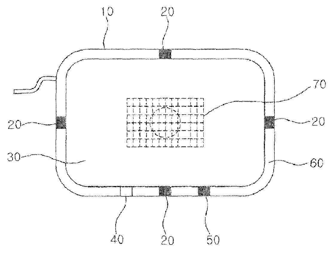
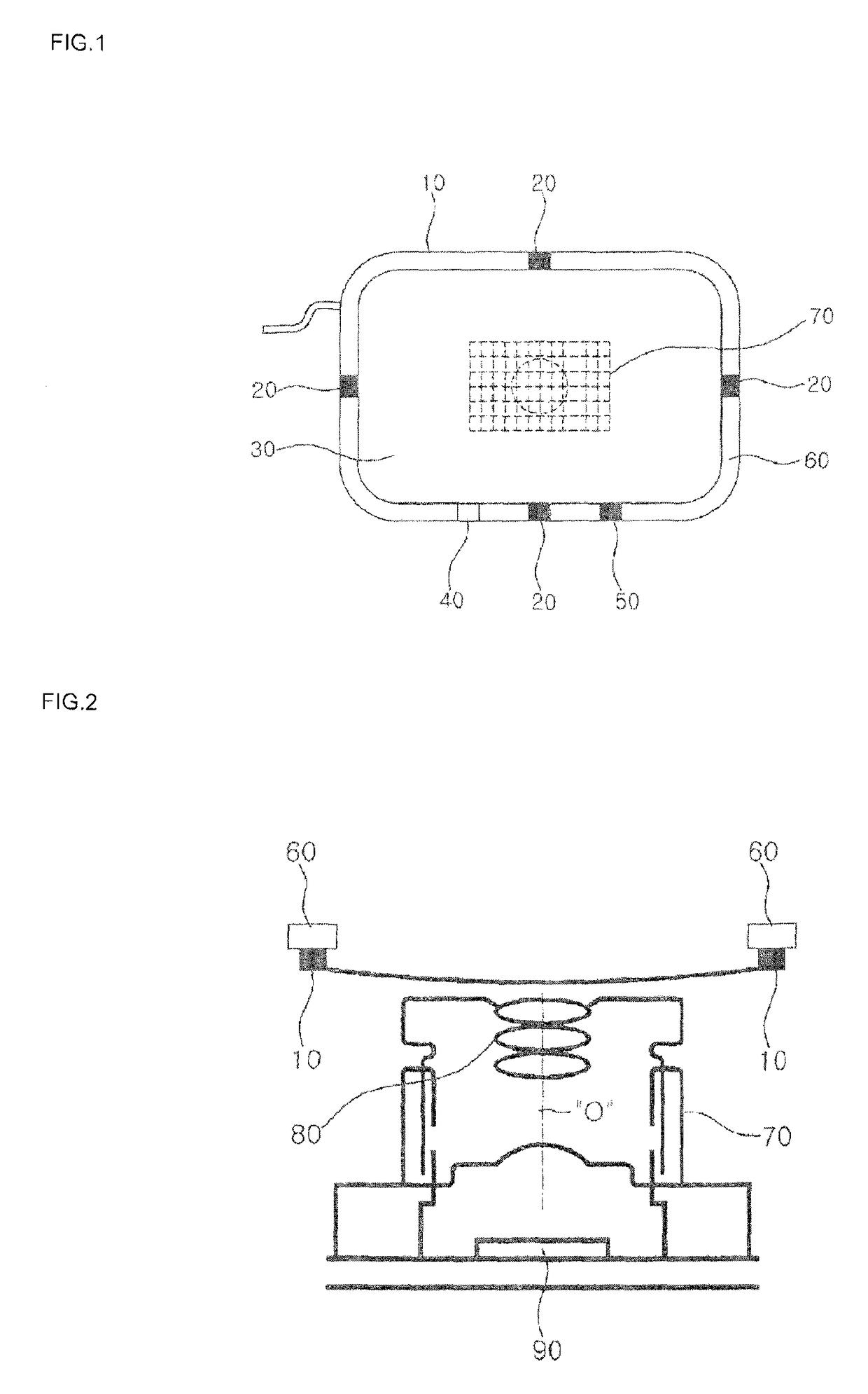
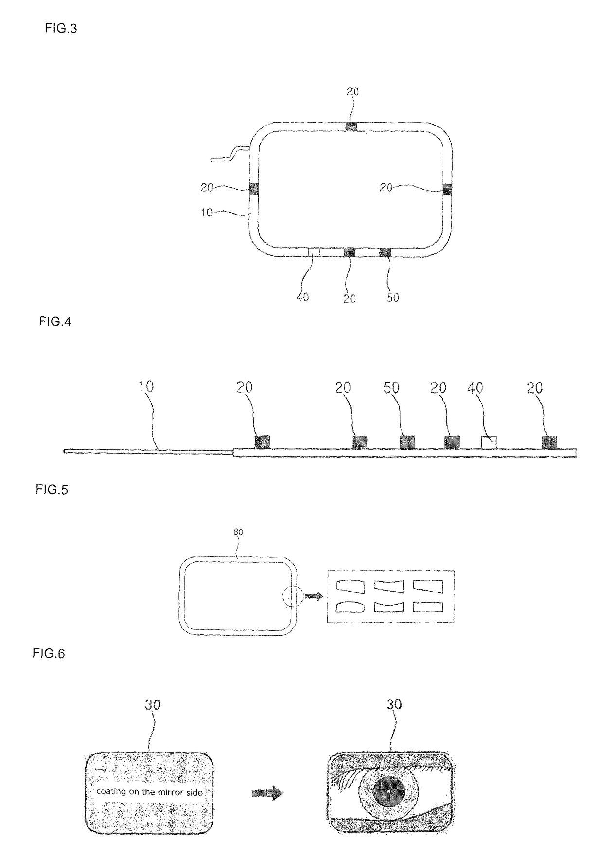
[0050]The key technological principle of the present invention is to enhance the uniformity of brightness in the vicinity of an iris then improve the iris recognition performance by equipping an IR LED light source element with an inclined surface in its upper and lower side or with an FPCB cover on which protrusions and depressions that diffuse or scatter light, to effectively prevent static electricity being discharged via an IR LED light source element into internal devices, to operate by identifying a real, biological eye and to minimize the size and volume of an iris image-acquiring camera by employing an elliptical mirror optimized as an iris-guiding mirror.

[0051]The present invention will now be described more specifically with reference to the following preferred embodiments, examples of which are illustrated in the accompanying drawings.

[0052]Any structure or size of a feature of the subject matter may be simplified unless it poses a problem for the description of the prese...


PUM


Abstract

An iris recognition camera system for mobile device includes a sensor and associated circuit, a lens and lighting sources including a lighting source element, a displaying light source element and IR LED light source elements, wherein the lighting sources are installed around the center of a camera lens with a certain clearance, and the lighting sources are attached on an FPCB and arranged on the four sides of the center of the camera lens and equipped with an FPCB cover for protection and a guiding mirror so that a user may conveniently acquire an image of his or her iris watching the image of his or her iris so as to identify and process only a living iris.

Description

BACKGROUND OF THE INVENTION[0001]The present invention relates to an iris recognition camera system for mobile devices which alloys a brightness and range of lighting and a direction of irradiation to be designed as desired by being equipped with an FPCB (flexible printed circuit board) on which an IR LED (infrared light-emitting diode) light source element is attached and with an FPCB cover (guide) either side of which has a concave-convex portion to scatter light or an FPCB cover of which materials contain a substance that scatters or diffuses light or of which surface is coated with such a substance, and also relates to an iris recognition system which is designed to effectively adjust the size of a camera by installing multiple (at least four) IR LED light source elements, which are aligned around a camera, on an FPCB, to ameliorate user convenience by visually displaying that iris recognition is being performed and to minimize the size and volume of a camera by employing an ell...

Claims


Application Information

Patent Timeline
Patent Type & Authority Patents(United States)
IPC IPC(8): H04N7/18G06K9/22G06K9/20G06K9/00H04N5/33H04N5/232H04N5/225G06V10/143G06V10/147G06V30/142
CPCG06K9/00604G06K9/209G06K9/2018H04N7/18H04N5/2256H04N5/23219H04N5/33G06K9/228G06V40/19G06V10/143G06V10/147G06V30/142H04N23/56H04N23/611G06V10/10
Inventor CHOI, KYUNG YONG
Owner CHOI KYUNG YONG
Why Eureka
Try Eureka