Check patentability & draft patents in minutes with Patsnap Eureka AI!

Waste water evaporator

a technology of evaporator and waste water, which is applied in the direction of evaporator regulation/control, separation process, treatment water nature, etc., can solve the problems of increasing environmental regulations and restrictions, affecting the use of conventional evaporation equipment and methods, and polluting soil and vegetation surrounding the storage pond, etc., to achieve the effect of reducing the corrosion of these components

Active Publication Date: 2017-11-28
E3 SOLUTIONS
View PDF10 Cites 1 Cited by
  • Summary
  • Abstract
  • Description
  • Claims
  • Application Information

AI Technical Summary

Benefits of technology

This patent describes systems and methods for efficiently and safely disposing of excess water from industrial and agricultural sources. The systems minimize drift caused by wind and spread the water droplets over a larger area, reducing the risk of wind carrying away the water. The housing, conduits, and hub are made from corrosion-resistant materials to prevent damage from the waste water. Overall, the patent provides a solution for managing waste water in a cost-effective and environmentally friendly way.

Problems solved by technology

Surplus waste water is a byproduct of many industrial and agricultural operations around the world and disposing of it in a responsible and affordable manner is a substantial issue for industry today.
However, more recently conventional evaporation equipment and methods have been found to be polluting the soil and vegetation surrounding the storage pond because the uncontrolled mist is drifting with wind conditions.
Environmental regulations and restrictions are on the rise and these conventional methods and equipment are being banned and restricted from use at an increasing rate around the world.
While these systems may move impressive volumes of fluid, it has been found that contaminants from the wastewater are simply drifting into surrounding trees and contaminating soil or being carried into the wind stream because true evaporation did not separate the toxic particles from the pure water.
However, as effective as these new fracturing and drilling methods are, there is a growing concern about the large amounts of water required for well production and the wastewater being generated therefrom.
In addition, increasing environmental regulations and concerns are limiting the options for safe, affordable and effective disposal of waste water.

Method used


Image

  • Waste water evaporator
  • Waste water evaporator
  • Waste water evaporator

Examples


Embodiment Construction

[0041]The subject matter of embodiments of the present invention is described here with specificity to meet statutory requirements, but this description is not necessarily intended to limit the scope of the claims. The claimed subject matter may be embodied in other ways, may include different elements or steps, and may be used in conjunction with other existing or future technologies. This description should not be interpreted as implying any particular order or arrangement among or between various steps or elements except when the order of individual steps or arrangement of elements is explicitly described.

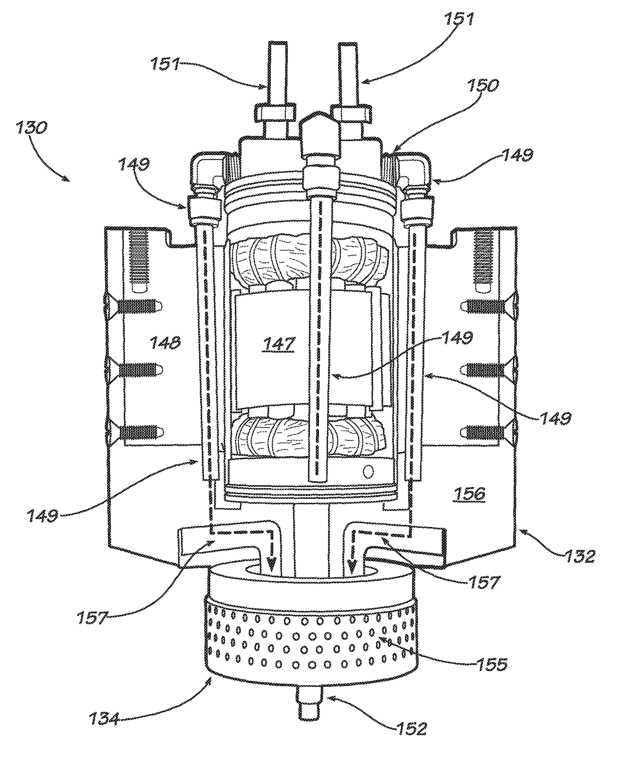
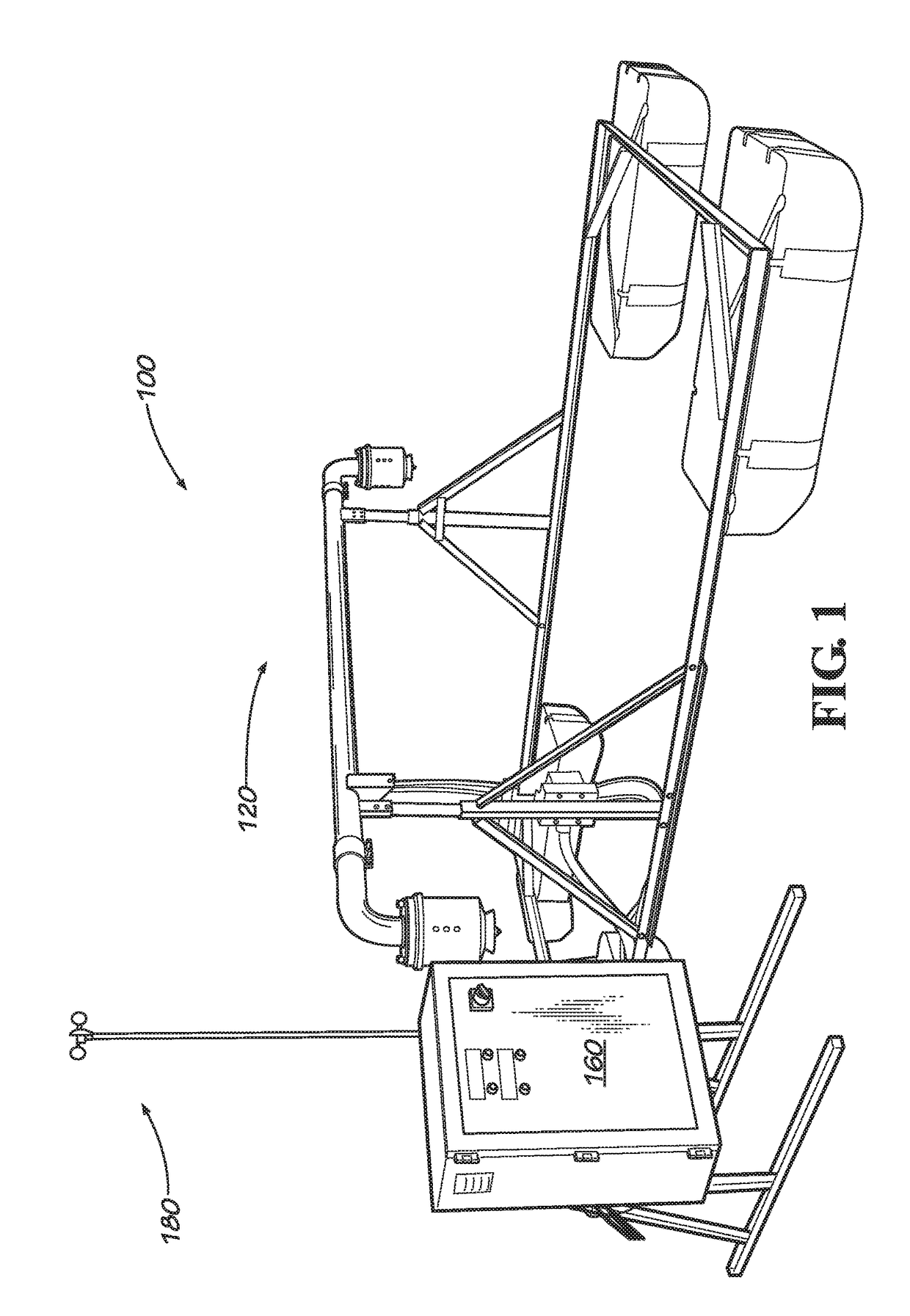
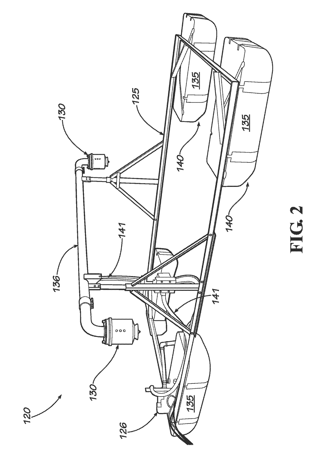
[0042]With reference to FIGS. 1 and 2, in one embodiment a water evaporator system 100 includes an atomizer assembly 120, a control system 160 and an anemometer 180.

[0043]The atomizer assembly 120 includes a frame 125 and at least one atomizer 130. The frame 125 may include at least one pontoon 135 for supporting the assembly 120 above the surface of a body of water such as a re...


PUM

PropertyMeasurementUnit
droplet sizeaaaaaaaaaa
perimeteraaaaaaaaaa

Abstract

An atomizer for use in waste water evaporation includes a motor having a rotor shaft, at least one conduit for receiving the waste water, a housing supporting the motor and the at least one conduit, and a hub having a plurality of holes for distributing waste water in the form of water droplets. The motor is a variable speed motor and is cooled by waste water flowing through the at least one conduit. The hub is connected to the rotor shaft and spins at a variable speed with the rotor shaft. The atomizer may be used in a waste water evaporation system that further includes an anemometer and a control system. The control system receives a wind speed input from the anemometer and provides a signal to the variable speed motor to adjust the speed of the variable speed motor and hub, thereby adjusting the water droplet size in response to varying wind conditions.

Description

CROSS REFERENCE TO RELATED APPLICATIONS[0001]This application is a divisional of U.S. patent application Ser. No. 13 / 836,541 entitled “Waste Water Evaporator” filed on Mar. 15, 2013, which is hereby incorporated by reference.FIELD OF THE INVENTION[0002]The present invention relates to the field of waste water evaporation, and more particularly to an evaporator system that promotes efficient evaporation of waste water from ponds such those found in industrial and agricultural operations while minimizing or eliminating environmental contamination problems from pollutants carried by wind drift.BACKGROUND[0003]Surplus waste water is a byproduct of many industrial and agricultural operations around the world and disposing of it in a responsible and affordable manner is a substantial issue for industry today. One of the most common and proven methods for reducing waste water involves using large evaporation ponds lined with black plastic where ambient temperatures and sunlight safely evap...

Claims


Application Information

Patent Timeline
Patent Type & Authority Patents(United States)
IPC IPC(8): C02F1/12B01B1/00B01D1/20B01D1/16C02F1/04B01D1/00C02F103/34
CPCC02F1/12B01B1/005B01D1/0082B01D1/20C02F1/048B01D1/16Y02W10/37C02F2103/34
Inventor NOEL, JAMEY SCOTTSULLIVAN, JEFFREY MORRISBLANCHARD, WILLIAM MCBRIDE
Owner E3 SOLUTIONS
Features
  • R&D
  • Intellectual Property
  • Life Sciences
  • Materials
  • Tech Scout
  • Unparalleled Data Quality
  • Higher Quality Content
  • 60% Fewer Hallucinations
Learn More