Control apparatus for vehicle

a technology for controlling apparatus and vehicle, applied in mechanical apparatus, transportation and packaging, gearing, etc., can solve problems such as inability to establish a desired gear stage, uplocks may occur, etc., to achieve effective external force, increase the probability of avoiding uplocks, and increase the rotation speed

Active Publication Date: 2017-11-28
TOYOTA JIDOSHA KK
View PDF10 Cites 4 Cited by
  • Summary
  • Abstract
  • Description
  • Claims
  • Application Information

AI Technical Summary

Benefits of technology

[0006]The invention provides a control apparatus for a vehicle, which is able to establish a desired gear stage by appropriately avoiding an uplock of a dog clutch even during a stop of the vehicle.
[0009]In the above aspect, the electronic control unit may be configured to, when the electronic control unit switches the transmission of power from the first transmission path to the second transmission path in a state where the vehicle is stopping or is stationary and in a state where power of the driving force source is transmitted to the drive wheel via the first transmission mechanism, release the first clutch mechanism and then engage the first clutch mechanism again. According to the above aspect, by releasing the first clutch mechanism, it is possible to rotate the driving force-side rotating member of the first clutch mechanism by the driving force source. By engaging the first clutch mechanism again in this state, it is possible to transmit power to the drive wheel-side rotating member of the dog clutch (in other words, it is possible to apply external force to the drive wheel-side rotating member of the dog clutch). Thus, it is possible to further rotate the drive wheel-side rotating member of the dog clutch, so it is possible to increase the probability of avoiding an uplock in the dog clutch at the time when the second clutch mechanism is actuated to the engaged side.
[0010]In the above aspect, the first transmission mechanism may be a continuously variable transmission mechanism. The first clutch mechanism may be provided on the drive wheel side with respect to the first transmission mechanism. The electronic control unit may be configured to, when the electronic control unit switches the transmission of power from the first transmission path to the second transmission path in a state where the vehicle is stopping or is stationary and in a state where power of the driving force source is transmitted to the drive wheel via the first transmission mechanism, upshift the first transmission mechanism in a state where the first clutch mechanism is released and then engage the first clutch mechanism again. According to the above aspect, by releasing the first clutch mechanism, it is possible to rotate the first transmission mechanism (continuously variable transmission mechanism) by the driving force source. In this state, by upshifting the continuously variable transmission mechanism, it is possible to increase the rotation speed on the drive wheel side of the continuously variable transmission mechanism. By engaging the first clutch mechanism again, it is possible to apply further large external force to the drive wheel-side rotating member of the dog clutch in comparison with the state where the continuously variable transmission mechanism is not upshifted. That is, it is possible to further effectively apply external force to the drive wheel-side rotating member of the dog clutch. Thus, it is possible to further reliably rotate the drive wheel-side rotating member of the dog clutch, so it is possible to further increase the probability of avoiding an uplock in the dog clutch at the time when the second clutch mechanism is actuated to the engaged side.

Problems solved by technology

However, when the sleeve is moved to mesh the spline teeth, an uplock may occur.
The uplock is such an engagement fault of the dog clutch (synchromesh mechanism) that the tooth tips of the spline teeth contact each other, so the spline teeth cannot be meshed with each, other, resulting in a state where the dog clutch is not engaged.
In such a case, it is not possible to establish a desired gear stage (speed stage).

Method used


Image

  • Control apparatus for vehicle
  • Control apparatus for vehicle
  • Control apparatus for vehicle

Examples


Embodiment Construction

[0022]Hereinafter, embodiments of the invention will be described in detail with reference to the accompanying drawings.

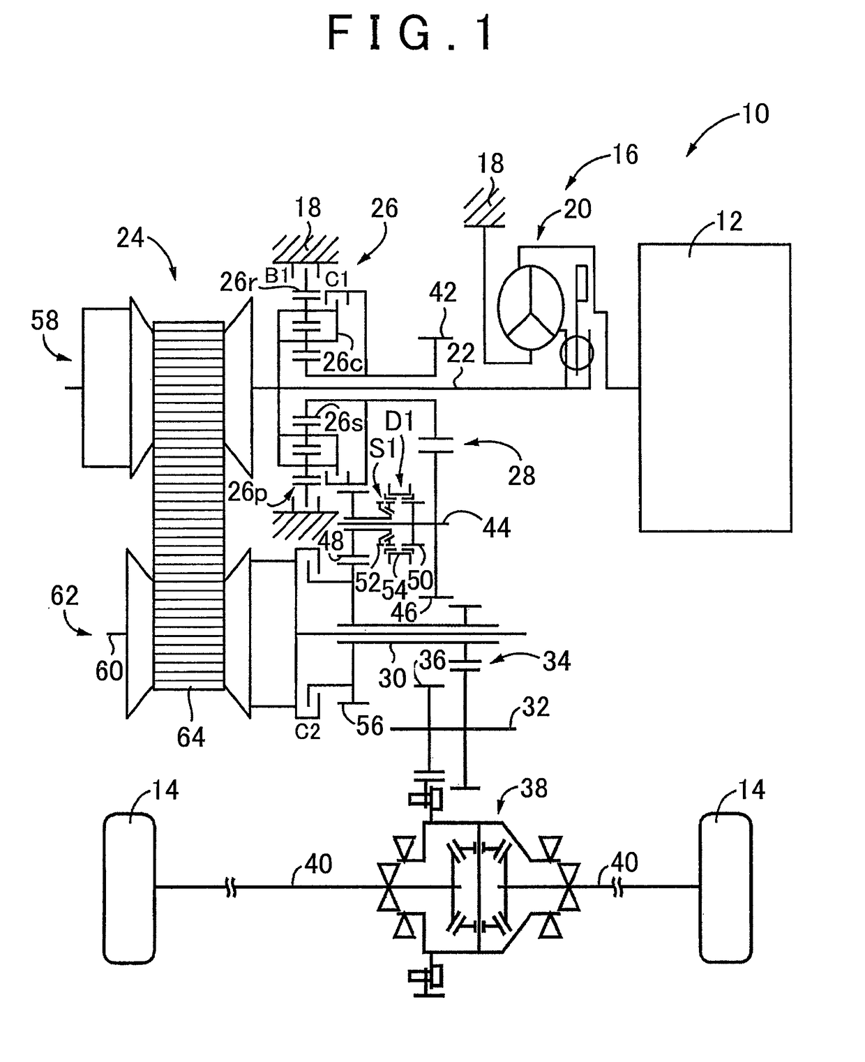
[0023]FIG. 1 is a view that illustrates the schematic configuration of a vehicle 10 to which the invention (first embodiment) is applied. As shown in FIG. 1, the vehicle 10 includes an engine 12, drive wheels 14 and a power transmission system 16. The engine 12 functions as a driving force source for propelling the vehicle 10. The power transmission system 16 is provided between the engine 12 and the drive wheels 14. The power transmission system 16 includes a known torque converter 20, an input shaft 22, a known belt-type continuously variable transmission 24 (hereinafter, referred to as continuously variable transmission 24), a forward / reverse switching device 26, a gear mechanism 28, an output shaft 30, a counter shaft 32, a reduction gear unit 34, a differential gear 38, a pair of axles 40, and the like. The torque converter 20 serves as a fluid transmission de...


PUM


Abstract

A first transmission mechanism provided on a first power transmission path and a second transmission mechanism provided on a second power transmission path are provided in parallel with each other between a driving force source and a drive wheel. A first clutch mechanism transmits power or interrupts transmission of power in the first power transmission path. A dog clutch equipped with a synchromesh mechanism transmits power or interrupts transmission of power in the second power transmission path. An electronic control unit is configured to, when changing from the first transmission path to the second transmission path a state where the vehicle is stopping or is stationary and in a state where power of the driving force source is transmitted via the first transmission mechanism, actuate the first clutch mechanism and the second clutch mechanism such that the first clutch mechanism is released and the second clutch mechanism engages.

Description

BACKGROUND OF THE INVENTION[0001]1. Field of the Invention[0002]The invention relates to a control apparatus for a vehicle including a first transmission mechanism and a second transmission mechanism provided in parallel with each other between a driving force source and a drive wheel.[0003]2. Description of Related Art[0004]There is well known a vehicle including a dog clutch equipped with a synchromesh mechanism. The dog clutch transmits power or interrupts transmission of power in a power transmission path that transmits power of a driving force source to a drive wheel side. This is, for example, the vehicle described in Japanese Patent Application Publication No. 2010-281423 (JP 2010-281423 A). JP 2010-281423 A describes that a target speed stage into which a speed stage is shifted is established by activating the synchromesh mechanism. That is, a synchronizer ring is pressed against a friction face of a cone of a synchronized-side gear (hereinafter, referred to as synchronized ...

Claims


Application Information

Patent Timeline
Patent Type & Authority Patents(United States)
IPC IPC(8): F16H61/02B60K17/08B60K17/16F16H61/04F16H37/02
CPCF16H61/0213B60K17/08B60K17/165F16H37/022F16H61/04F16H2061/0474F16H2037/026F16H2061/0234F16H2061/047F16H61/16F16H61/18F16H2710/00
Inventor NITANI, HIROMITSUAYABE, ATSUSHISAKAMOTO, KAZUYAKONDO, HIROKIFUKAO, MITSUHIROMATSUO, KENJI
Owner TOYOTA JIDOSHA KK
Why Eureka
Try Eureka