
Method and apparatus for evaporating organic working media

a technology of organic working media and evaporation apparatus, which is applied in the direction of lighting and heating apparatus, mixers, steam generation using hot heat carriers, etc., can solve the problems of reducing the efficiency of the plant, so as to achieve the effect of greater flexibility

Active Publication Date: 2017-11-28
ORCAN ENERGY AG
View PDF29 Cites 30 Cited by
  • Summary
  • Abstract
  • Description
  • Claims
  • Application Information

AI Technical Summary

Benefits of technology

The invention relates to a method and apparatus for controlling the temperature of a heat-supplying medium in a heat exchanger. The technical effects of the invention include preventing the decomposition of the organic working medium, ensuring a homogenous mixing of components in the hot flue gas and cooled flue gas, and allowing greater flexibility in adjusting the mixing temperature of the heat-supplying medium. Additionally, the invention allows for heating or cooling of the heat-supplying medium after it has flown out of the heat exchanger and before it is supplied to the flow of the heat-supplying medium supplied from the heat source to the evaporator.

Problems solved by technology

In comparison with water organic media have clearly lower decomposition temperatures, however, i.e. temperatures at which the molecular bonds of the medium break, which results in the destruction of the working medium and in the decomposition into corrosive or poisonous reaction products.
Also, a failure of the feed pump entails that the flow through the heat exchanger is interrupted, so that the working medium is directly exposed to the temperature of the heat source employed for the evaporation.
Firstly, thermal oils are typically combustible.
Therefore, to avoid the oxidation of the thermal oil, the thermal oil cycle has to be provided with a primary nitrogen pressure, which renders the plant technically complicated and expensive.
In addition, thermal oils are subject to aging owing to the high thermal load, and have to be replaced at regular intervals.
This results in down times of the plant, and in increased costs.

Method used


Image

  • Method and apparatus for evaporating organic working media
  • Method and apparatus for evaporating organic working media
  • Method and apparatus for evaporating organic working media

Examples


Embodiment Construction

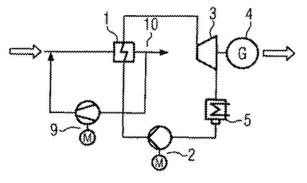
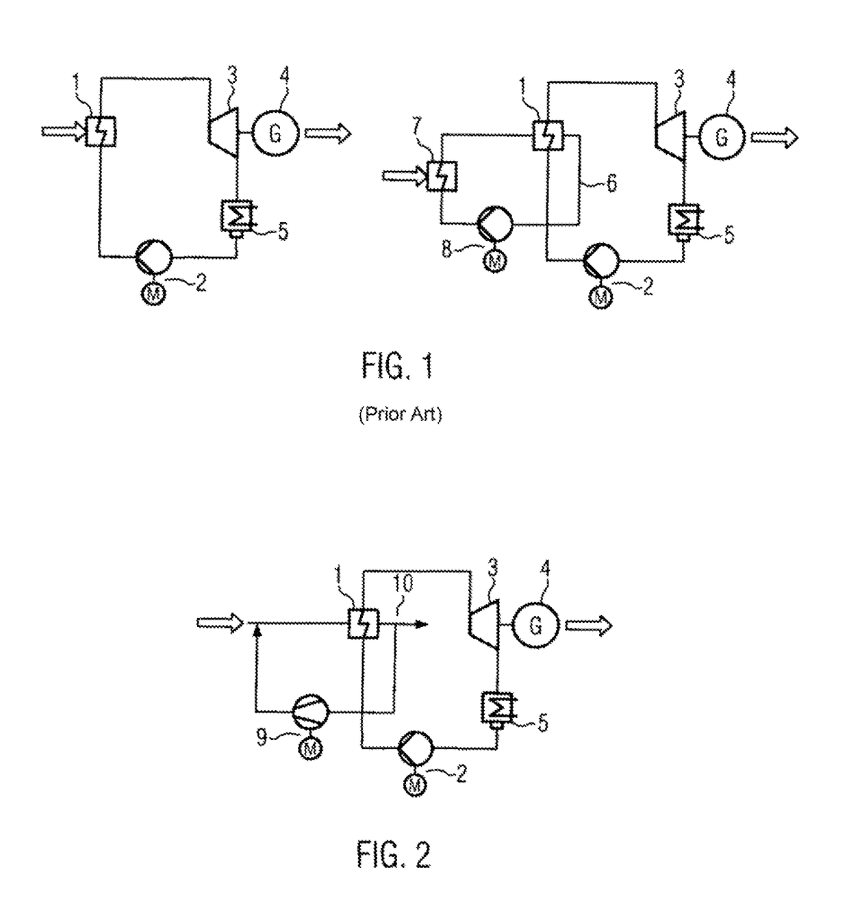
[0029]FIG. 1 shows a conventional ORC plant based on direct evaporation (left) and including an intermediate cycle (right). An evaporator 1 acting as a heat exchanger is supplied with heat from a heat source (not shown), e.g. by a flue gas which is produced in the combustion of a fuel, as is shown by the left arrow in the left part of FIG. 1. In the evaporator 1 heat is supplied to a working medium supplied by a feed pump 2. It is, for instance, fully evaporated, or evaporated by means of flash evaporation downstream of the heat exchanger. The working medium vapor is conducted through a pressure pipe to a turbine 3. In the turbine the working media vapor is expanded, and the turbine 3 drives a generator 4 to gain electric energy (illustrated by the right arrow in FIG. 1). The expanded working medium vapor is condensed in a condenser 5, and the liquified working medium is supplied by the feed pump back to the evaporator 1.

[0030]If an intermediate cycle 6 is used, as is shown in the r...


PUM


Abstract

The present invention provides a device which comprises: a heat exchanger (1) for transferring heat of a heat-supplying medium to a working medium which differs from said heat-supplying medium, a first supply device designed to provide a flow of the heat-supplying medium at a first temperature from a heat source to the heat exchanger, and a second supply device which is designed to deliver the heat-supplying medium after it has passed through the heat exchanger, and / or a further medium at a second temperature lower than the first temperature, to the flow of the heat-supplying medium at the first temperature.

Description

FIELD OF THE INVENTION[0001]The present invention relates to an apparatus for the direct evaporation of organic working media, for the generation of electric energy from heat sources through the use of organic media.BACKGROUND OF THE INVENTION[0002]The operation of expansion machines, such as steam turbines, by means of the Organic Rankine Cycle (ORC) method for the generation of electric energy through the use of organic media, e.g. organic media having a low evaporation temperature, which generally have higher evaporation pressures at the same temperatures as compared to water as working medium, is known in the prior art. ORC plants constitute a realization of the Rankine cycle in which electric energy is basically obtained, for instance, by means of adibatic and isobaric changes of condition of a working medium. Mechanical energy is generated by the evaporation, expansion and subsequent condensation of the working medium, and is converted into electric energy. Basically, the work...

Claims


Application Information

Patent Timeline
Patent Type & Authority Patents(United States)
IPC IPC(8): F22B1/18F01K25/10B01F5/04F22B35/00
CPCF22B1/18F22B35/002F01K25/10B01F5/0485B01F25/31425
Inventor AUMANN, RICHARDSCHUSTER, ANDREASSICHERT, ANDREAS
Owner ORCAN ENERGY AG
Learn More