Elevator system including a power storage device with a supercapacitor unit and a battery unit

a supercapacitor unit and elevator technology, applied in elevators, mine lifts, sustainable buildings, etc., can solve the problems of inefficient regenerative recovery, difficult to take advantage of the power regenerated by the elevator system, and relatively short service life of acid batteries. , to achieve the effect of short installation time, competitive cost and significant energy saving

Active Publication Date: 2017-12-05
OTIS ELEVATOR CO
View PDF27 Cites 17 Cited by
  • Summary
  • Abstract
  • Description
  • Claims
  • Application Information

AI Technical Summary

Benefits of technology

[0014]The present elevator system can be implemented in a “new equipment” form or in a modernization / retrofit form. In the new equipment form, the elevator system is specifically designed for and implemented in a new building. In the modernization / retrofit form, an existing elevator system is modified according to the present invention, or the present elevator system is utilized in an existing building, respectively. In any of these embodiments, the present invention system can add valuable new features like blackout mode operation, and offer significant energy savings at a competitive cost and with short installation time.

Problems solved by technology

Unfortunately, lead acid batteries typically have a relatively short service life, and are inefficient at regeneratively recovering high power peaks that are available when an elevator is operating in a braking phase.
These two factors make it difficult to take advantage of power regenerated by an elevator system.
These types of batteries can however, be prohibitively expensive when configured to cover significant periods of blackout mode operation in a low rise residential application.
Unfortunately, the current battery market does not offer a single device that can store sufficient energy to cover all the requirements discussed above, at a price that is competitive in the low rise residential market.

Method used


Image

  • Elevator system including a power storage device with a supercapacitor unit and a battery unit
  • Elevator system including a power storage device with a supercapacitor unit and a battery unit
  • Elevator system including a power storage device with a supercapacitor unit and a battery unit

Examples


Embodiment Construction

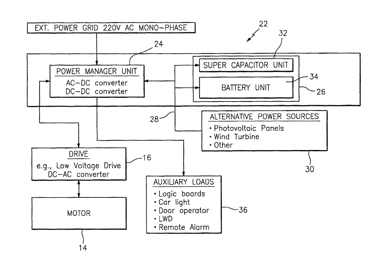
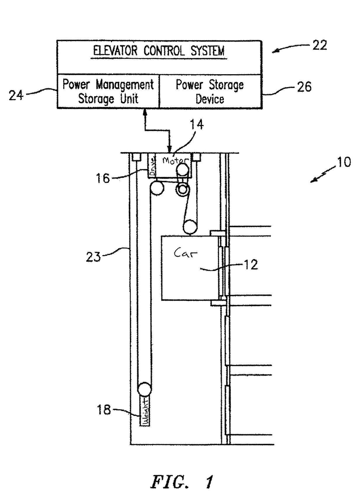
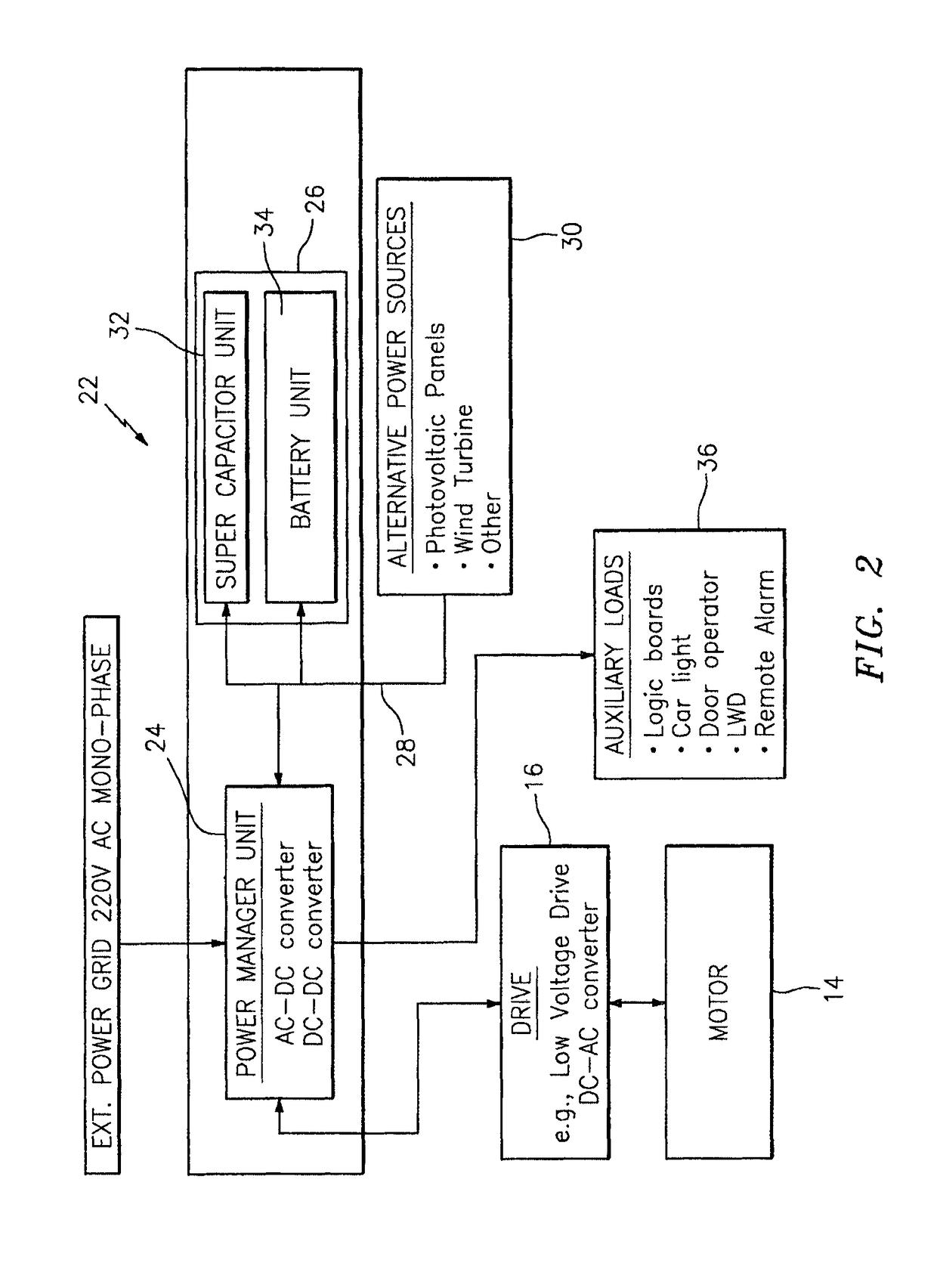
[0018]Referring to FIG. 1, an elevator system 10 is schematically shown that includes an elevator car 12, an elevator motor 14 and drive 16, a counterweight 18, and an elevator control system 22, for operation within a hoistway 23. The control system 22 includes circuitry operable to provide electrical power to electrical components within the elevator system 10, and includes a power manager unit 24, and a power storage device 26. In some embodiments, the elevator control system 22 also includes hardware 28 (see FIG. 2) for connecting to one or more alternative power sources 30.

[0019]Referring to FIGS. FIGS. 1-3, the elevator motor 14 and drive 16 are configured to selectively produce regenerative power, for example, during a braking mode as is known in the art. In most elevator systems, the counterweight 18 is given a weight that is approximately equal to the weight of the elevator car 12 with a moderate load (e.g., half the rated load). Consequently, when a less than moderately lo...


PUM


Abstract

An elevator system is provided that includes an elevator car, a counterweight, a load bearing flexible member, a motor having a drive, and an elevator control system. The car and counterweight are operable to be translated within a hoistway. The load bearing flexible member extends between the elevator car and the counterweight. The motor is operable to move the load bearing member and thereby drive the elevator car and counterweight within the hoistway. The elevator motor and drive are configured to selectively produce regenerative power. The elevator control system includes a power manager unit and a power storage device. The power storage device includes a supercapacitor unit and a battery unit. The power manager unit is operable to selectively manage the flow of power between the power storage device and the motor drive, and the flow of regenerative power from the motor drive to the power storage device.

Description

[0001]This application is entitled to the benefit of, and incorporates by reference essential subject matter disclosed in PCT Application No. PCT / IT2012 / 000167 filed on Jun. 1, 2012.BACKGROUND OF THE INVENTION[0002]Technical Field[0003]The present invention relates to the supply of electrical power to an elevator system in general, and to devices capable of storing electrical power for an elevator in particular.[0004]Background Information[0005]In some applications, according to the local energy market and grid power quality, it is desirable to equip a grid-powered elevator with an energy accumulation device that can be accessed during peak power demand periods or periods when grid power is not available (i.e., blackout mode).[0006]This accumulation device can be also used, to regeneratively recover energy when the elevator is operating in a braking phase in order to achieve a better performance in terms of energy efficiency, and also greater duration when operating in blackout mode...

Claims


Application Information

Patent Timeline
Patent Type & Authority Patents(United States)
IPC IPC(8): B66B1/08B66B1/30B66B19/00
CPCB66B1/306B66B1/302Y02B50/142B66B19/007Y02B50/00
Inventor MEZZADRI, CARLOFOSCHINI, GLANLUCACOLOMBARI, CARLO
Owner OTIS ELEVATOR CO
Why Eureka
Try Eureka