
Control unit for a piece of furniture

a technology for controlling units and furniture, which is applied in the direction of computer control, instruments, sofas, etc., can solve the problems of no longer receiving control data, no longer being decoded or even decoded, and affecting the operation of the control unit, so as to achieve greater operating reliability and greater comfort. the effect of operation

Active Publication Date: 2017-12-05
DEWERTOKIN TECHNOLOGY GROUP CO LTD
View PDF6 Cites 12 Cited by
  • Summary
  • Abstract
  • Description
  • Claims
  • Application Information

AI Technical Summary

Benefits of technology

The present invention aims to improve the existing control unit and operating unit to enhance user comfort and reliability. The integrated control unit and operating unit can communicate wirelessly, making it easier for users to connect the two devices. This eliminates the need for manual pairing and switches on the control unit, providing a more seamless user experience.

Problems solved by technology

This is in particular because of the unidirectional wireless transmission link, on which disturbances due to interference and other noise effects can corrupt control data emitted from the operating unit such that they can no longer be decoded or are even no longer receivable by the control unit.
In particular in the case of actions which react comparatively slowly to emitted control data, for example, turning on a heater connected to the control unit, this is annoying for the user.

Method used


Image

  • Control unit for a piece of furniture
  • Control unit for a piece of furniture
  • Control unit for a piece of furniture

Examples


Embodiment Construction

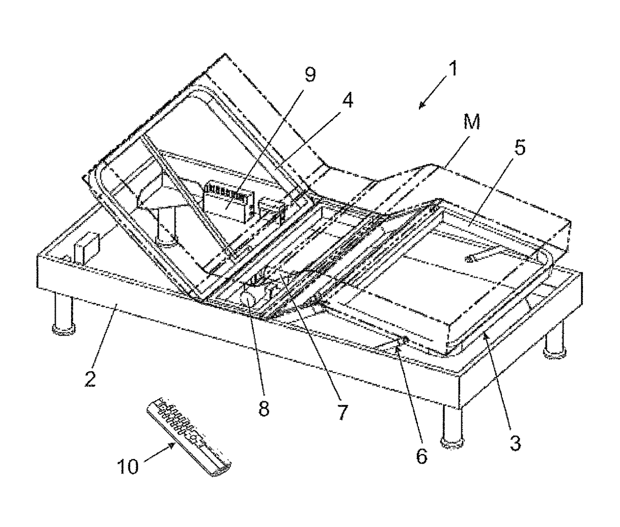
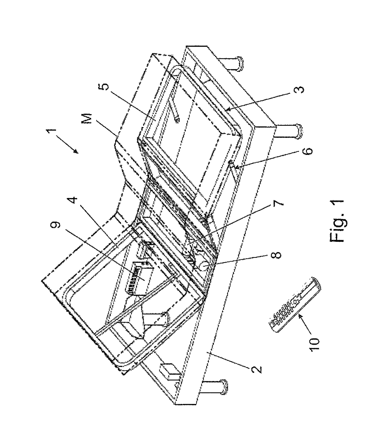
[0031]FIG. 1 shows an exemplary furniture assembly having a piece of furniture 1. A schematic perspective view of an operating unit 10 is shown in FIG. 2.

[0032]The piece of furniture 1 is shown here as a bed and has at least one support element 3 for accommodating objects, a cushion, a mattress M, and / or a person. The support element 3 is implemented, for example, as a slatted frame, as a level support surface, or the like and is attached to a base element 2, here a framework having feet, for coupling the piece of furniture 1 to a setup location, for example, a floor.

[0033]The support element 3 has here a back part 4 and a leg part 5, which are arranged movably mounted in relation to a further support element or in relation to the base element 2. This movable arrangement is implemented here by means of a so-called movement fitting 6. The movement is implemented as displaceable and / or pivotable.

[0034]The movably mounted back part 4 and the leg part 5 are each coupled to an electromot...


PUM


Abstract

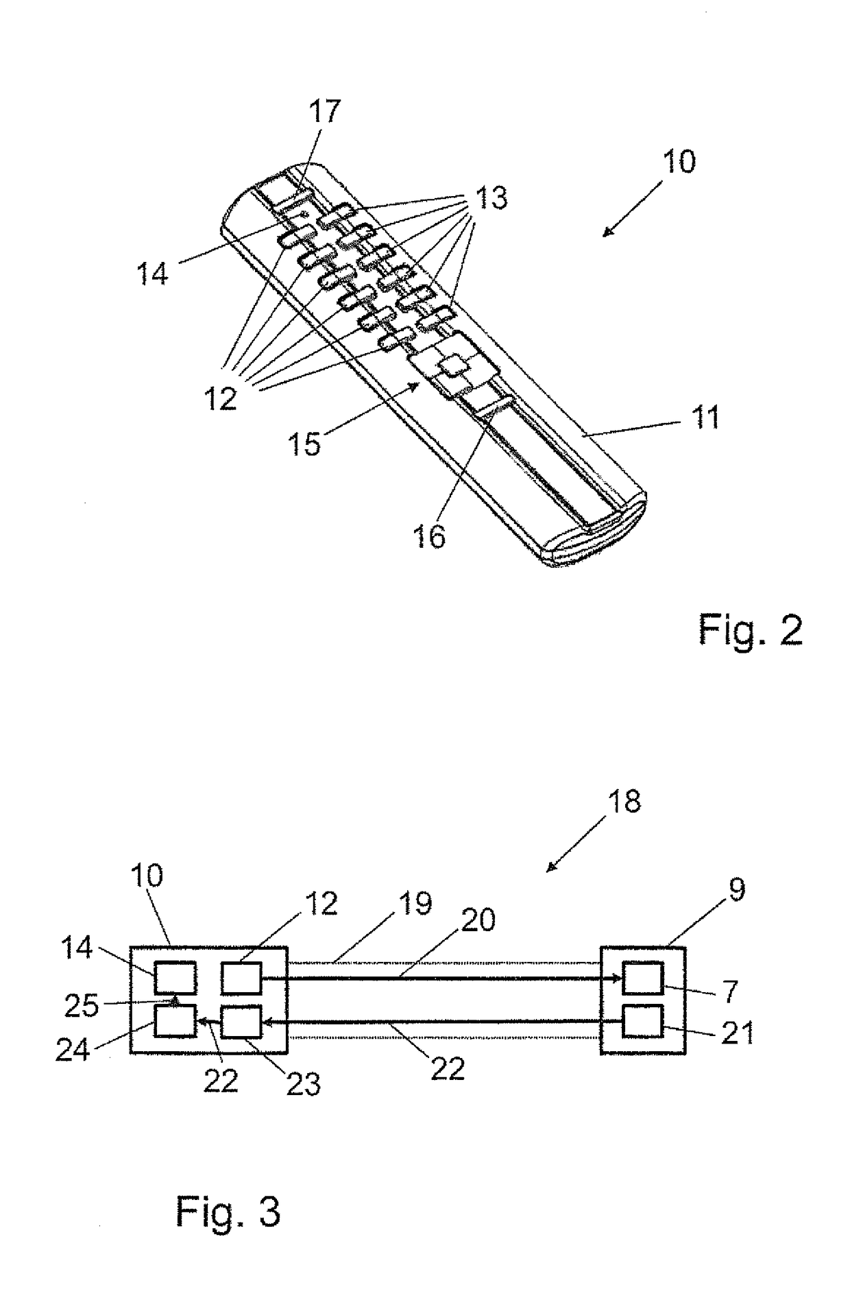
The invention relates to a control device (9) for at least one adjusting drive (7, 8) which is to be associated with a piece of furniture (1) and which is designed to control the at least one adjusting drive (7, 8) based on control data (20) captured by a wireless transmission path (19) of the operating unit (10). Said control device is characterized by an emitter interface (21) which is designed to transmit data (22) to the operating unit (10) by means of a wireless transmission path (19). The invention further relates to an operating unit (10) comprising a receiver interface (23) which is designed to capture data (22) from the control device (9) by means of a wireless transmission path (19), in addition to a system (18) consisting of a control device (9) and an operating unit (10) and a piece of furniture (1) equipped with said system (13).

Description

CROSS-REFERENCES TO RELATED APPLICATIONS[0001]This application is the U.S. National Stage of International Application No. PCT / 2013 / 054101, filed Feb. 28, 2013, which designated the United States and has been published as International Publication No. WO 2013 / 127961 and which claims the priority of German Patent Application, Serial No. 10 2012 101 627.5, filed Feb. 28, 2012, pursuant to 35 U.S.C. 119(a)-(d).BACKGROUND OF THE INVENTION[0002]The invention relates to a control unit for at least one adjustment drive to be arranged in a piece of furniture, wherein the control unit is configured to activate the at least one adjustment drive based on control data received via a wireless transmission link from an operating unit.[0003]Adjustment drives, frequently also referred to as electromotive furniture drives, are installed in reclining furniture and seating furniture to be able to comfortably move an adjustment of the furniture parts such as seats, backrests, footrests, etc. in relatio...

Claims


Application Information

Patent Timeline
IPC IPC(8): G01M1/38H04W88/00G05B15/02A47C20/04A47C31/00
CPCG05B15/02H04W88/00A47C31/008A47C20/041
Inventor HILLE, ARMINLOLEY, STEFFENGEHRKE, KARSTEN
Owner DEWERTOKIN TECHNOLOGY GROUP CO LTD
Learn More