
Handler with integrated receiver and signal path interface to tester

a receiver and signal path technology, applied in the direction of transmission monitoring, line-transmission details, instruments, etc., can solve the problem of complex electronic systems of systems

Active Publication Date: 2017-12-05
ADVANTEST CORP
View PDF18 Cites 3 Cited by
  • Summary
  • Abstract
  • Description
  • Claims
  • Application Information

AI Technical Summary

Benefits of technology

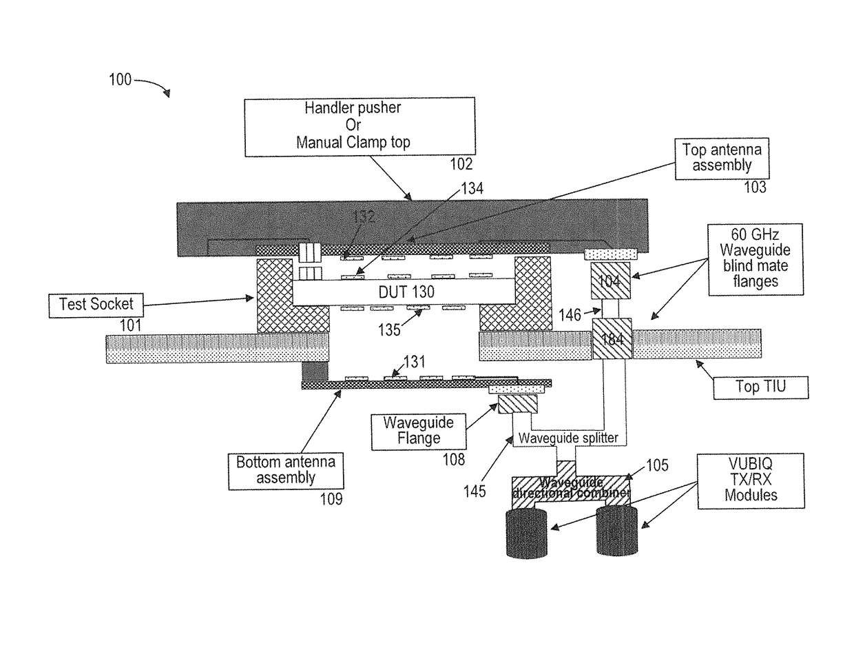
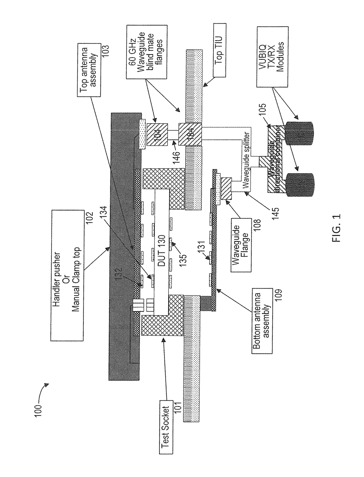
This patent text describes a device that can test signals from microwave antennas on semiconductor devices. The device has a recorder and a waveguide that work together to channel signals from the antennae to the test fixture. This makes it easy to test the performance of the semiconductor device in the microwave bandwidth. The technical effect of this patent is that it provides a convenient and efficient way to test microwave signals from semiconductor devices.

Problems solved by technology

Conventional ATE systems are very complex electronic systems and generally include printed circuit boards (PCB), coax cables and waveguides to extend the signal path of test signals transmitted from the DUT to a tester diagnostic system during a test session.
The advent of high frequency wireless applications e.g., WiGig applications, however, requires the testing of DUTs that communicate wirelessly at multi-gigabit speeds, which is problematic for conventional ATE systems.
However, when the DUT contains patch antennae located at the top, this is problematic for testing because the receivers located at the test fixture may not be able to receive the signals for testing for any one of several reasons.
For example, the receivers may be too far away from the DUT, the top patch antennae may be radiating wireless signals in a direction opposite from the receivers on the test fixture, or the handler electronics may be interfering with the signal reception.

Method used


Image

  • Handler with integrated receiver and signal path interface to tester
  • Handler with integrated receiver and signal path interface to tester
  • Handler with integrated receiver and signal path interface to tester

Examples


Embodiment Construction

[0021]Reference will now be made in detail to the various embodiments of the present disclosure, examples of which are illustrated in the accompanying drawings. While described in conjunction with these embodiments, it will be understood that they are not intended to limit the disclosure to these embodiments. On the contrary, the disclosure is intended to cover alternatives, modifications and equivalents, which may be included within the spirit and scope of the disclosure as defined by the appended claims. Furthermore, in the following detailed description of the present disclosure, numerous specific details are set forth in order to provide a thorough understanding of the present disclosure. However, it will be understood that the present disclosure may be practiced without these specific details. In other instances, well-known methods, procedures, components, and circuits have not been described in detail so as not to unnecessarily obscure aspects of the present disclosure.

[0022]A...


PUM


Abstract

A method for testing a device under test (DUT) is disclosed. The method comprises communicating signals wirelessly from a first plurality of patch antennae disposed on a top surface of the DUT to a second plurality of patch antennae disposed on a printed circuited within a handler device, wherein the handler device is operable to place the DUT in a socket of a tester system, and wherein the tester system comprises the handler device and a test fixture. The method further comprises communicating the signals captured by the second plurality of patch antennae using microstrip transmission lines to a patch antenna on the printed circuit board, wherein a first waveguide is mounted to the patch antenna using a first waveguide flange, and wherein the first waveguide flange is coupled to a first end of the first waveguide.

Description

FIELD OF THE INVENTION[0001]Embodiments of the present disclosure generally relate to Automatic Test Equipment (ATE) for testing electronic components.BACKGROUND[0002]Automatic Test Equipment (ATE) is commonly used within the field of electronic chip manufacturing for the purposes of testing electronic components. ATE systems both reduce the amount of time spent on testing devices to ensure that the device functions as designed and serve as a diagnostic tool to determine the presence of faulty components within a given device before it reaches the consumer.[0003]ATE systems can perform a number of test functions on a device under test (DUT) through the use of test signals transmitted to and from the DUT. Conventional ATE systems are very complex electronic systems and generally include printed circuit boards (PCB), coax cables and waveguides to extend the signal path of test signals transmitted from the DUT to a tester diagnostic system during a test session. Conventional ATE system...

Claims


Application Information

Patent Timeline
Patent Type & Authority Patents(United States)
IPC IPC(8): H04B17/00H04B3/46H04B3/52H04B17/12
CPCH04B3/46H04B17/12H04B3/52G01R1/0408G01R31/3025
Inventor LAM, DANIEL
Owner ADVANTEST CORP
Learn More