Accessory mount for turf or grounds care equipment

a technology for accessory mounts and which is applied in the direction of lawn mowers, agricultural machines, agricultural tools and machines, etc., can solve the problems that accessories cannot be readily interchanged between mowers or other turf or grounds care equipment from different manufacturers, and achieve the effect of reducing distan

Active Publication Date: 2017-12-12
BRINLY-HARDY COMPANY
View PDF22 Cites 11 Cited by
  • Summary
  • Abstract
  • Description
  • Claims
  • Application Information

AI Technical Summary

Benefits of technology

[0013]Once the lateral bar is the desired distance from the mower (or other turf or grounds care equipment), the fasteners of the clamping assemblies are tightened, reducing the distance between the base panels of the U-shaped member, such that the first and second clamping assemblies are pressed into secure frictional engagement with the first and second arms.
[0014]Advantageously, the frictional engagement between the clamping assemblies and the first and second arms provides a safe “failure point” if the mower (or other turf or grounds care equipment) strikes an object. Specifically, if an accessory strikes an object, the clamping assemblies can slide along the first and second arms to absorb the impact. In this way, some other portion of the accessory mount, the accessory, or the mower is protected from potential damage. The clamping assemblies can then be returned to the original position to continue operation of the mower.

Problems solved by technology

However, because each manufacturer constructs the mower differently, accessories often cannot be readily interchanged between mowers or other turf or grounds care equipment from different manufacturers.

Method used


Image

  • Accessory mount for turf or grounds care equipment
  • Accessory mount for turf or grounds care equipment
  • Accessory mount for turf or grounds care equipment

Examples


Embodiment Construction

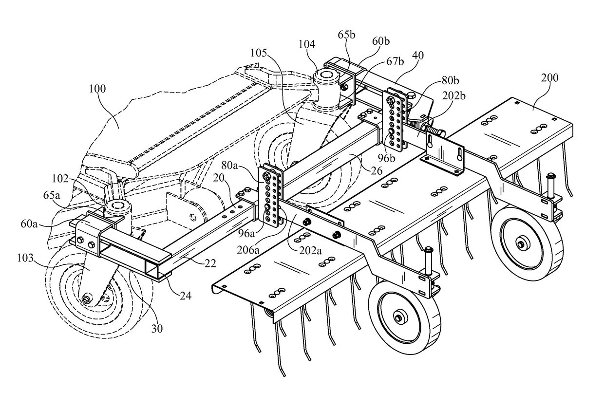
[0020]The present invention is an accessory mount for turf or grounds care equipment, such as a zero-turn radius mower. In particular, the present invention is an accessory mount for turf or grounds care equipment, such as a zero-turn radius mower, that is adjustable, such that it can be installed on mowers or other turf or grounds care equipment that are not provided with any framework for securing such accessories, or it can be installed on mowers or other turf or grounds care equipment from different manufacturers.

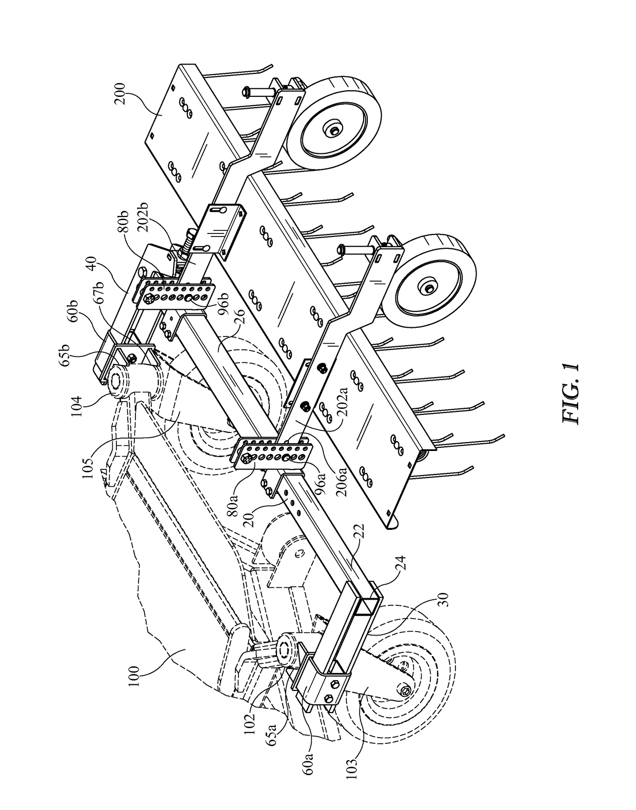
[0021]Referring to FIG. 1, a typical zero-turn radius mower 100 includes two front casters 103, 105. The wheel of each caster 103, 105 is supported by a bracket. The bracket includes a vertical shaft that is received in and supported by a frame portion 102, 104 that is part of or is secured to the mower 100, thus mounting each caster 103, 105 to the mower 100. In particular, as shown in FIG. 1, a first frame portion 102 mounts a first caster 103, and a second frame port...


PUM


Abstract

An accessory mount comprises: a lateral bar having a first end and a second end opposite the first end; a first arm connected to the first end of the lateral bar and terminating in a distal end; and a second arm pivotally connected to the second end of the lateral bar and terminating in a distal end. The first and second arms of the accessory mount are configured to engage respective frame portions of a mower or other turf or grounds care equipment, and the pivoting or movement of the second arm relative to the lateral bar adjusts a distance between the distal end of the first arm and the distal end of the second arm. A first clamping assembly may be connected to the first arm, and a second clamping assembly may be connected to the second arm to engage the respective frame portions of the article of turf or grounds care equipment.

Description

CROSS-REFERENCE TO RELATED APPLICATIONS[0001]The present application claims priority to U.S. Patent Application Ser. No. 62 / 016,887 filed on Jun. 25, 2014.BACKGROUND OF THE INVENTION[0002]The present invention is an accessory mount for turf or grounds care equipment, such as a zero-turn radius mower.[0003]Zero-turn radius mowers are commonly used by turf and grounds care professionals for mowing grass, but, in many cases, it is desirable to attach a turf and grounds care accessory to the mower to complete other jobs. Similarly, it is often desirable to attach an accessory to other types of mowers or turf or grounds care equipment. One such accessory is a dethatcher which runs a series of metal blades, tines, or prongs along the ground to remove dead grass, leaves, stems, and the like. Other accessories include, but are not limited to, an aerator, lawn roller, fertilizer spreader, storage cart, or the like. Zero-turn radius mowers and other turf or grounds care equipment made by diff...

Claims


Application Information

Patent Timeline
Patent Type & Authority Patents(United States)
IPC IPC(8): A01B76/00A01B45/00A01B45/02A01D42/00
CPCA01B76/00A01B45/00A01B45/02A01D42/00A01B35/06A01B35/24A01D43/02
Inventor SNYDER, CHRISCHASTEEN, RONNIE
Owner BRINLY-HARDY COMPANY
Why Eureka
Try Eureka