Device and method for mitral valve regurgitation treatment

a technology of mitral valve and device, applied in the field of medical devices, can solve the problems of affecting the effectiveness of the heart to pump adequate blood into other parts of the body, affecting the function of the mitral valve, so as to achieve the effect of effective security

Active Publication Date: 2017-12-12
SINOMED CARDIOVITA TECH INC
View PDF12 Cites 71 Cited by
  • Summary
  • Abstract
  • Description
  • Claims
  • Application Information

AI Technical Summary

Benefits of technology

[0010]It is an object of the present invention to provide a mitral valve replacement device that can be effectively secured to the location of the human mitral valve annulus without piercing of the native tissue.
[0011]It is another object of the present invention to provide a method of deploying a mitral valve replacement device at the location of the human mitral valve annulus where the position of the device can be adjusted before final release of the device is completed.
[0012]It is yet another object of the present invention to provide a novel leaflet structure that provides more efficient valvular control and flow.

Problems solved by technology

Regardless of the cause, the regurgitation interferes with heart function since it allows blood to flow back through the valve in the wrong direction.
Depending on the degree of regurgitation, this backflow can become a self-destructive influence on not only the function, but also on the cardiac geometry.
Depending on the severity of the leakage, the effectiveness of the heart to pump adequate blood flow into other parts of the body can be compromised.
Because of the invasive nature of the surgical procedure, risks of death, stroke, bleeding, respiratory problems, renal problems, and other complications are significant enough to exclude many patients from surgical treatment.
None of the existing medical devices to date address this need fully.

Method used


Image

  • Device and method for mitral valve regurgitation treatment
  • Device and method for mitral valve regurgitation treatment
  • Device and method for mitral valve regurgitation treatment

Examples


first embodiment

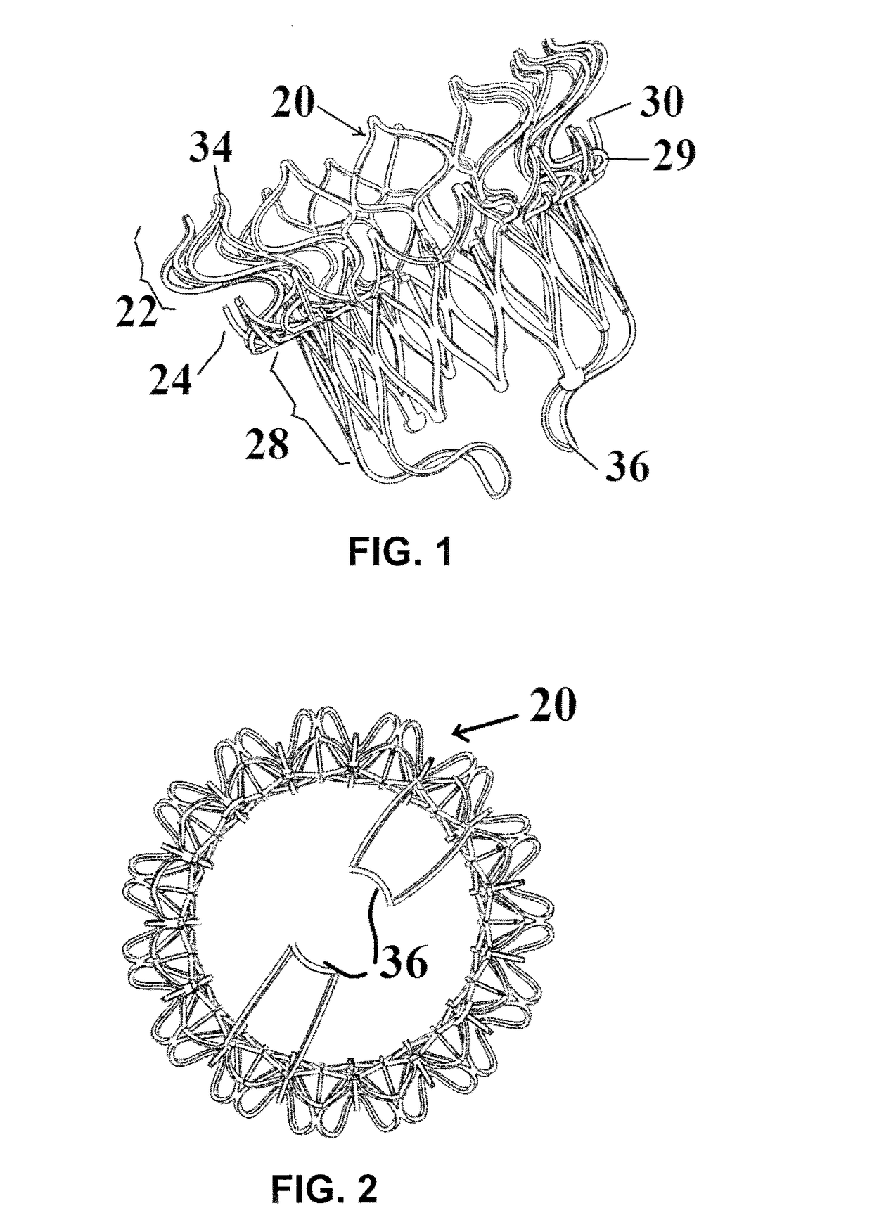
[0052]FIGS. 1-5 illustrate a mitral valve device 20 according to the present invention. The device 20 has an atrial flange 22, an annulus support 24, a neck section 26 that connects the atrial flange 22 to the annulus support 24, and a valve body 28 that functions as a leaflet supporting structure. Each of these components is defined by struts that define cells that in turn make up a cellular matrix.

[0053]The atrial flange 22, the annulus support 24 and the valve body 28 can be made from either a Nitinol superelastic material or stainless steel, Co—Cr based alloy, Titanium and its alloys, and other balloon expandable biocompatible materials. Other polymer biocompatible materials can also be used to fabricate these components of the device 20. In use, the device 20 can be folded or compacted into a delivery system and delivered to the location of the mitral valve through transcatheter delivery (e.g., transfemoral or transapical). Once at the location of the mitral valve, the device 2...

second embodiment

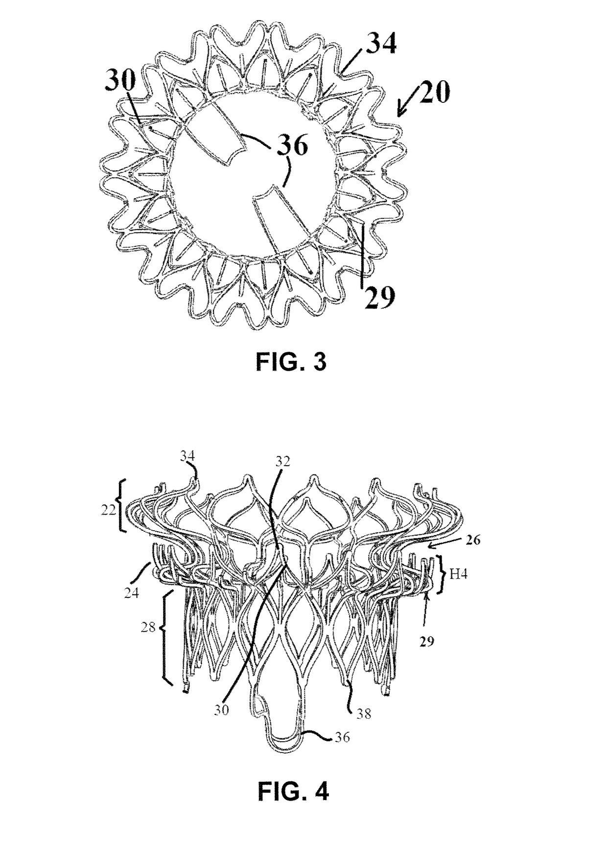
[0066]FIGS. 12-14 illustrate a mitral valve device 20 according to the present invention, which includes the addition of clips 80. The device 20 in FIGS. 12-14 also have an atrial flange 22, an annulus support 24, a neck section 26 that connects the atrial flange 22 to the annulus support 24, and a valve body 28 that functions as a leaflet supporting structure, all of which can be the same as the corresponding elements in FIGS. 1-5. Each of these components is also defined by struts that define cells that in turn make up a cellular matrix.

[0067]The difference between the two embodiments is the addition of a ring of clips 80 that are provided in spaced-apart manner around the valve body 28 at a location spaced vertically below the annulus support 24. These clips 80 are somewhat L-shaped in that each clip 80 can extend vertically from any of the struts in the valve body 28, then horizontally in a radial direction before terminating in a short bend at its tip. The clips 80 function to ...

third embodiment

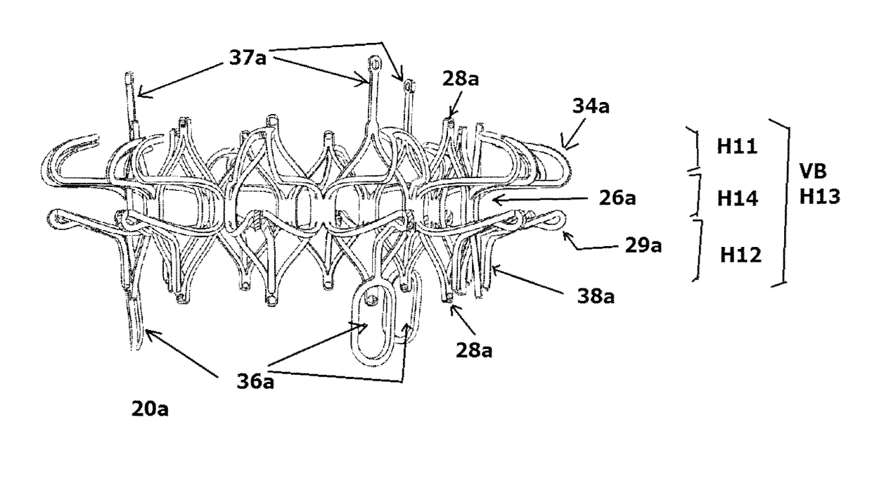
[0070]FIGS. 16-22 illustrate a mitral valve device 20a according to the present invention. The device 20a in FIGS. 16-22 also has an atrial flange 22a, an annulus support 24a, and a neck section 26a that connects the atrial flange 22a to the annulus support 24a. The valve body VB is now defined by the atrial flange 22a, the annulus support 24a, and a ventricular portion that is defined by V-shaped tabs 28a.

[0071]The atrial flange 22a is similar to the atrial flange 22, except that the atrial flange 22a may have a lower profile. A ring of spaced-apart inverted V-shaped tabs 34a defines peaks and valleys for the atrial flange 22a, with a rounded non-traumatic tip 35a at each peak thereof. A plurality of leaflet holders or posts 37a extends from selected tips 35a, and each functions to support and hold portions of the leaflet. Each post 37a can be straight or curved.

[0072]The atrial flange 22a can be placed at or on the native annulus of the mitral valve, with a portion of the atrial ...


PUM


Abstract

A mitral valve replacement device is adapted to be deployed at a mitral valve position in a human heart. The device has an atrial flange defining an atrial end of the device, a ventricular portion defining a ventricular end of the device, the ventricular portion having a height ranging between 2 mm to 15 mm, and an annulus support that is positioned between the atrial flange and the ventricular portion. The annulus support includes a ring of anchors extending radially therefrom, with an annular clipping space defined between the atrial flange and the ring of anchors. A plurality of leaflet holders positioned at the atrial end of the atrial flange, and a plurality of valve leaflets secured to the leaflet holders, and positioned inside the atrial flange at a location above the native annulus.

Description

RELATED CASES[0001]This application is related to Provisional Application No. 62 / 024,097, filed Jul. 14, 2014, Provisional Application No. 61 / 927,490, filed Jan. 15, 2014, and Provisional Application No. 61 / 887,343, filed Oct. 5, 2013. This application is a continuation-in-part of U.S. application Ser. No. 14 / 279,511, filed May 16, 2014, whose entire disclosure is incorporated by this reference as though set forth fully herein.BACKGROUND OF THE INVENTION[0002]1. Field of the Invention[0003]The present invention generally relates to medical devices and methods useful for human mitral valve function repair and / or reconstruction. In particular, the present invention relates to a medical device that can be used to treat mitral valve regurgitation by replacing the function of native heart valves.[0004]2. Description of the Prior Art[0005]The human heart has four chambers and four valves. The heart valves control the direction of blood flow. Fully-functional heart valves ensure proper blo...

Claims


Application Information

Patent Timeline
Patent Type & Authority Patents(United States)
IPC IPC(8): A61F2/24
CPCA61F2/24A61F2/2412A61F2/2418A61F2230/005A61F2210/0014A61F2220/005A61F2220/0008A61F2/2409A61F2230/0052A61F2250/0039
Inventor MA, JIANLUHUO, YONGLI, TIANZHUZHAO, JINHONGMA, JIANXIANGMENG, LEI
Owner SINOMED CARDIOVITA TECH INC
Why Eureka
Try Eureka