
Gas turbine system with a transition duct having axially extending cooling channels

a transition duct and cooling channel technology, applied in the direction of machines/engines, stators, light and heating equipment, etc., can solve the problems of significant uncertainty in the cooling air distribution and negatively affect the aim of meeting low nox emissions, and achieve the effect of adjusting the cooling efficiency and mechanical robustness of the transition duct, low cost, and easy production

Active Publication Date: 2017-12-12
SIEMENS ENERGY GLOBAL GMBH & CO KG
View PDF17 Cites 3 Cited by
  • Summary
  • Abstract
  • Description
  • Claims
  • Application Information

AI Technical Summary

Benefits of technology

The present invention provides a gas turbine system with an improved structure for reducing NOx emissions over a broad load range. This is achieved by designing cooling air channels that improve the distribution of cooling air and reduce cooling air consumption. The ends of neighboring cooling air channels are staggered to increase mechanical robustness of the transition duct. The number, length, flow cross section, and direction of each cooling air channel, as well as their relative positions, can be adjusted to improve cooling efficiency and mechanical robustness. The transition duct has a three layer bonded panel design with elongated cutouts and holes for the cooling air channels, which simplifies production at low costs. The combustion chamber is inserted in the transition duct to simplify assembly of the gas turbine system.

Problems solved by technology

Such a cooling air channel design has the drawback that the cooling air distribution has a significant uncertainty due to the multiple inlets and outlets, which needs to be covered by additional cooling air.
However, additional cooling air negatively affects the aim to meet low NOx emissions.

Method used


Image

  • Gas turbine system with a transition duct having axially extending cooling channels
  • Gas turbine system with a transition duct having axially extending cooling channels
  • Gas turbine system with a transition duct having axially extending cooling channels

Examples


Embodiment Construction

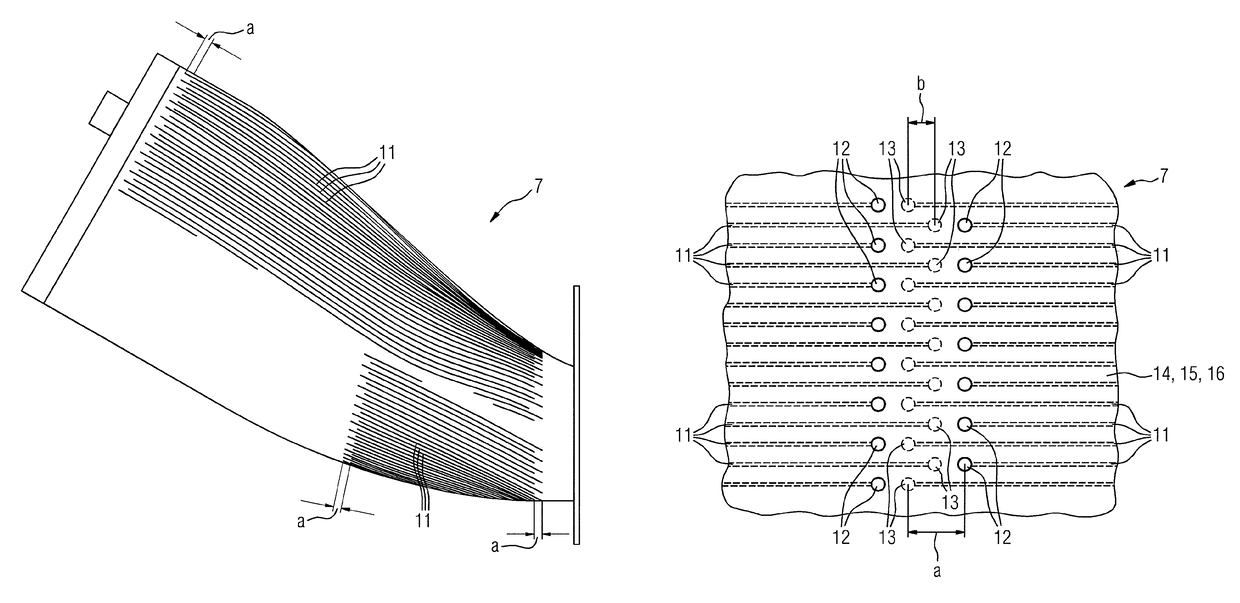
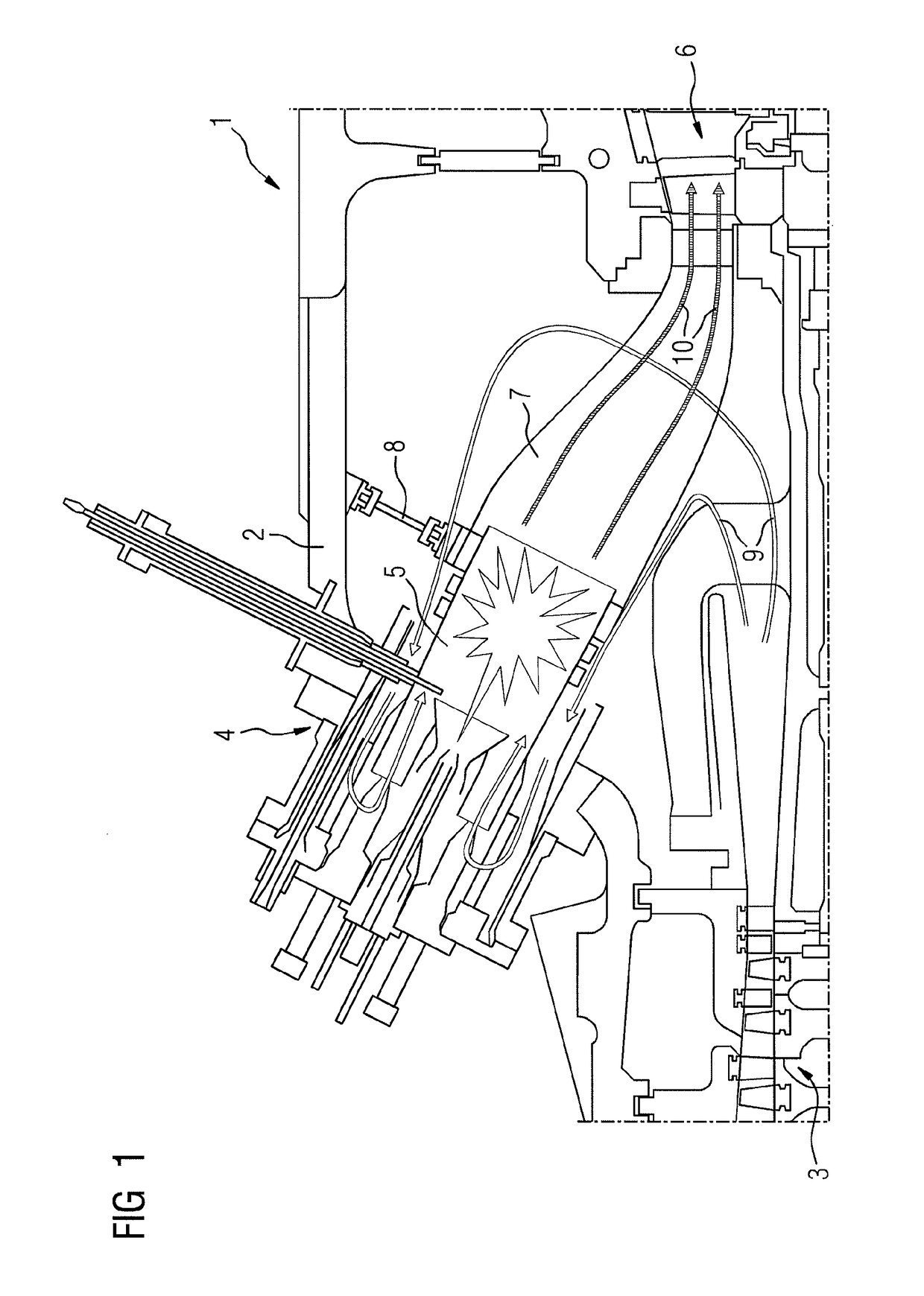
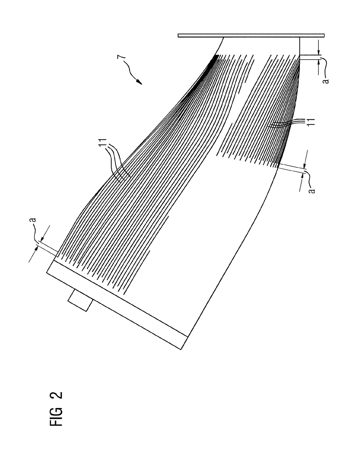
[0033]FIG. 1 shows a gas turbine system 1 according to an embodiment of the present invention. The gas turbine system 1 comprises a multi-part housing 2, a compressor 3 arranged within the housing 2, a burner arrangement 4, which is fixed to the housing 2 and is provided with a combustion chamber 5, a turbine 6 arranged within the housing 2 and a transition duct 7 connecting the combustion chamber 5 and the turbine 6. During the assembly of the gas turbine system 1, the transition duct 7 is connected to the turbine 6. Moreover, the transition duct 7 is adjusted and fixed to the housing 2 by means of a fixture 8. Subsequently the burner arrangement 4 is inserted in the housing through an associated opening of the housing, whereupon the free end of the combustion chamber 5 is entered in the transition duct 7. Afterwards the combustion chamber 5 and the transition duct 7 are adjusted to each other, and the burner arrangement 4 is fixed to the housing 2.

[0034]During operation of the gas...


PUM


Abstract

A gas turbine system (1) including a burner arrangement having a tubular combustion chamber (5), a turbine (6) and a transition duct (7) connecting the combustion chamber (5) and the turbine (6), wherein the transition duct (7) is provided with an axially extending cooling air channel (11). The transition duct (7) includes a plurality of axially extending cooling air channels, and wherein each cooling air channel (11) is provided with one single inlet (12) opened to the outside of the transition duct (7) and with one single outlet (12) opened to the inside of the transition duct (7).

Description

TECHNICAL FIELD[0001]The present invention relates to a gas turbine system comprising a burner arrangement having a tubular combustion chamber, a turbine and a transition duct connecting the combustion chamber and the turbine, wherein the transition duct is provided with an axially extending cooling air channel.TECHNICAL BACKGROUND[0002]Gas turbine systems of the above mentioned kind are known in prior art. During the operation, ambient air is compressed and directed towards the burner arrangement. Inside the burner arrangement the compressed air is mixed with fuel, and the created fuel-air-mixture is ignited within the combustion chamber to generate hot combustion gases, which are directed towards the turbine via the transition duct. The turbine extracts rotational energy from the hot combustion gases and drives a load, such as a generator.[0003]With increasing operating temperatures it is often necessary to cool components of a gas turbine system in order to counteract a limitatio...

Claims


Application Information

Patent Timeline
Patent Type & Authority Patents(United States)
IPC IPC(8): F01D9/02F23R3/02F23R3/00F23R3/04F02C7/18F23R3/06F23R3/08F01D25/12
CPCF01D9/023F23R3/002F23R3/005F23R3/02F23R3/04F23R3/06F02C7/18F23R2900/03045F01D25/12F05D2260/202F05D2260/204F23R3/08F23R2900/00017F23R2900/03041F23R2900/03042F23R2900/03043F23R2900/03044
Inventor HASE, MATTHIASSANDERS, PAUL A.KRISHNAN, VAIDYANATHAN
Owner SIEMENS ENERGY GLOBAL GMBH & CO KG
Learn More