System and methods for monitoring leaks in underground storage tanks

a technology for underground storage tanks and leakage detection, applied in the field of leak detection systems and methods, can solve problems affecting the efficiency of ms ion traps, and achieve the effect of simplifying user operation and improving leakage detection speed

Active Publication Date: 2017-12-12
LEAK DETECTION TECH INC
View PDF69 Cites 2 Cited by
  • Summary
  • Abstract
  • Description
  • Claims
  • Application Information

AI Technical Summary

Benefits of technology

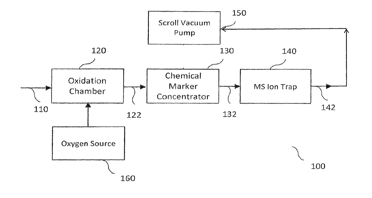
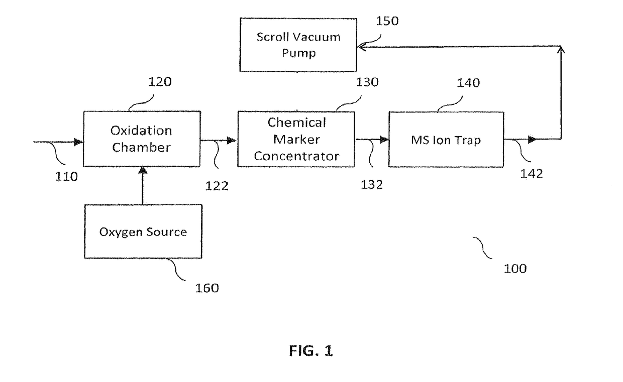
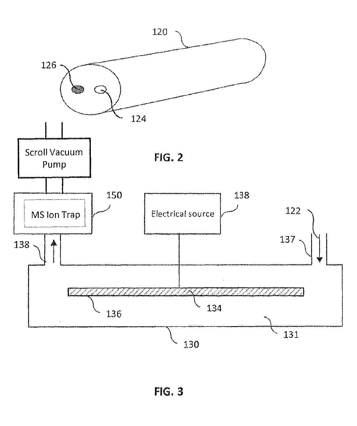
[0007]In one embodiment, the oxidation chamber comprises a solid metal body with a conduit containing a dry chemical through which the vapor is passed, and an imbedded heating element. The heating element permits rapid and controlled heating for the conduit to a desired temperature. By heating the oxidation chamber to a precise predetermined temperature, the dry chemical in an atmosphere of oxygen absorbs and destroys the contaminates while allowing the markers to pass through without being destroyed. This process of destroying the contaminates with little or negligible degradation of the markers allows the mass ion trap to identify the chemical markers with little or no interference in the signal from the contaminates.
[0010]Accordingly, embodiments provided by this disclosure may advantageously result in improved leakage detection speed and simplified user operation as compared to conventional detection method utilizing a gas chromatography (GC) equipment.

Problems solved by technology

Samples are taken in the area surrounding the containment and may have or had hydrocarbon contamination which will affect the efficiency of the MS Ion Trap.

Method used


Image

  • System and methods for monitoring leaks in underground storage tanks
  • System and methods for monitoring leaks in underground storage tanks
  • System and methods for monitoring leaks in underground storage tanks

Examples


Embodiment Construction

[0018]In the following description, for the purpose of explanation, specific details are set forth in order to provide understanding of the present invention. However, the present invention may be implemented without some of these details. The embodiments of the present invention described below may be incorporated into a number of different means, components, apparatus, circuits and devices. Structures and devices shown in block diagram are illustrative of exemplary embodiments of the present invention. Connections between components may be modified, re-formatted via intermediary components. When the specification makes reference to “one embodiment” or to “an embodiment”, it is intended to mean that a particular feature, structure, characteristic, or function described in connection with the embodiment being discussed is included in at least one contemplated embodiment of the present invention. Thus, the appearance of the phrase, “in one embodiment” in different places in the speci...


PUM

PropertyMeasurementUnit
temperatureaaaaaaaaaa
mass spectrometeraaaaaaaaaa

Abstract

Leak detection system and method for monitoring leaks in underground and aboveground storage tanks, pipelines or other containments, including single, double or triple wall containments are provided. A leak detection apparatus includes an oxidation chamber, a chemical marker concentrator, a mass spectrometer (MS) ion trap and a scroll vacuum pump. Vapor samples carrying marker chemicals introduced into a tank, pipeline, or other containment are injected at sample injection point into an oxidation chamber. Oxygen from an oxygen source is fed into oxidation chamber to destroy or oxidize contaminates such as hydrocarbons in the vapor without destroying or oxidizing the chemical markers. Effluent from the oxidation chamber is passed to an elongate conduit with a metal foil or screen suspended within the conduit. The marker chemicals are attracted by a chemical coating on the foil / screen and released by heating the metal. The released marker chemicals are fed into a mass spec ion trap for leakage analysis and results.

Description

FIELD OF THE DISCLOSURE[0001]The present disclosure is generally related to leak detection system and method, and more particularly is related to system and method for monitoring leaks in aboveground and underground containments such as pipelines, storage tanks and the like.BACKGROUND OF THE DISCLOSURE[0002]Underground and aboveground containments have been used in various applications, such as in the petroleum, nuclear, and laboratory industry. Those containments need to be monitored for leakage prior to or during usage. Systems for monitoring and detecting the location of leaks in underground storage tanks and pipelines have been described.[0003]U.S. Pat. No. 4,709,577 describes a fluorinated halocarbon compound tracer with a boiling point less than that of gasoline. The tracer is slowly dispensed within the tank. A sampling pipe having a plurality of apertures is buried in selected locations in the vicinity of the tank, and samples of the soil gas are pumped from the pipe and sup...

Claims


Application Information

Patent Timeline
Patent Type & Authority Patents(United States)
IPC IPC(8): G01N1/40G01M3/20G01N30/12G01N27/16
CPCG01M3/205G01N2030/125G01N27/16G01N1/40G01M3/22
Inventor RABB, DAVID M.HUEY, KENNETH H.
Owner LEAK DETECTION TECH INC
Why Eureka
Try Eureka