Check patentability & draft patents in minutes with Patsnap Eureka AI!

HVAC unit identification device and method

a technology of unit identification and identification device, which is applied in the field of heating, ventilation and air conditioning, can solve problems such as loud clicking nois

Inactive Publication Date: 2017-12-26
JONES RAY
View PDF4 Cites 0 Cited by
  • Summary
  • Abstract
  • Description
  • Claims
  • Application Information

AI Technical Summary

Benefits of technology

Enables a single technician to efficiently identify the correct outdoor unit, reducing repair costs and improving operational efficiency by using a device that connects to existing thermostat wires and operates from either thermostat power or a battery, compatible with both heat pump and cooling-only systems.

Problems solved by technology

The result of this pulsing of the reversing valve is a loud clicking noise.

Method used


Image

  • HVAC unit identification device and method
  • HVAC unit identification device and method
  • HVAC unit identification device and method

Examples


Embodiment Construction

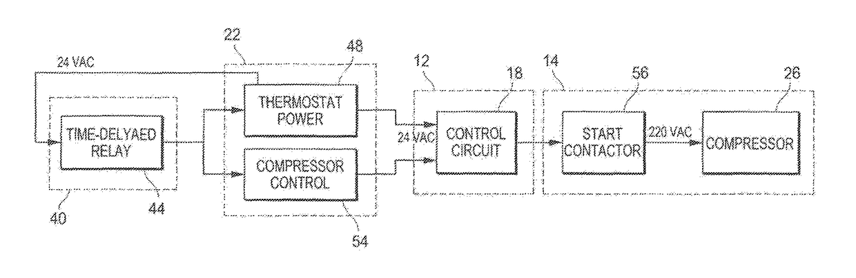
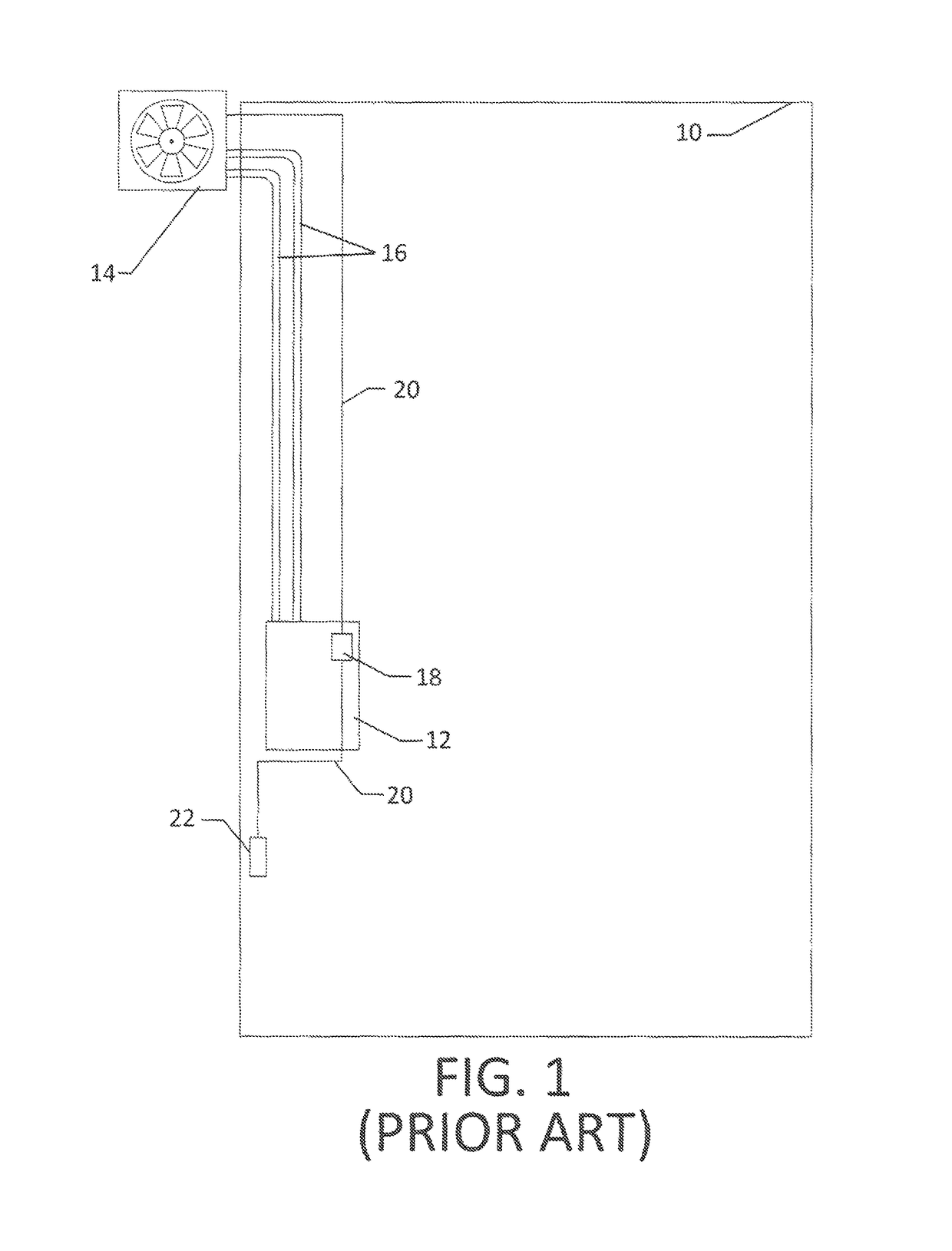
[0028]The present invention uses an electrical or electromechanical device, such as a time delayed relay driven by a fixed voltage, to pulse the control lines of an HVAC unit. The pulse generating device may be referred to as a “pulse generator.”FIG. 1 shows a schematic of a prior art split HVAC system in a dwelling 10. This is a typical setup for an HVAC system found in a home or apartment. The split system has an inside unit 12 and an outside unit 14 that may sit behind or on top of the dwelling 10.

[0029]The preferred embodiment of the present invention is attached to the thermostat 22. It pulses the control lines 20. These lines lead to control circuit 18 contained within inside unit 12. Control lines 20 then run from inside dwelling 10 to outside unit 14, activating the correct mechanism as described in the succeeding text.

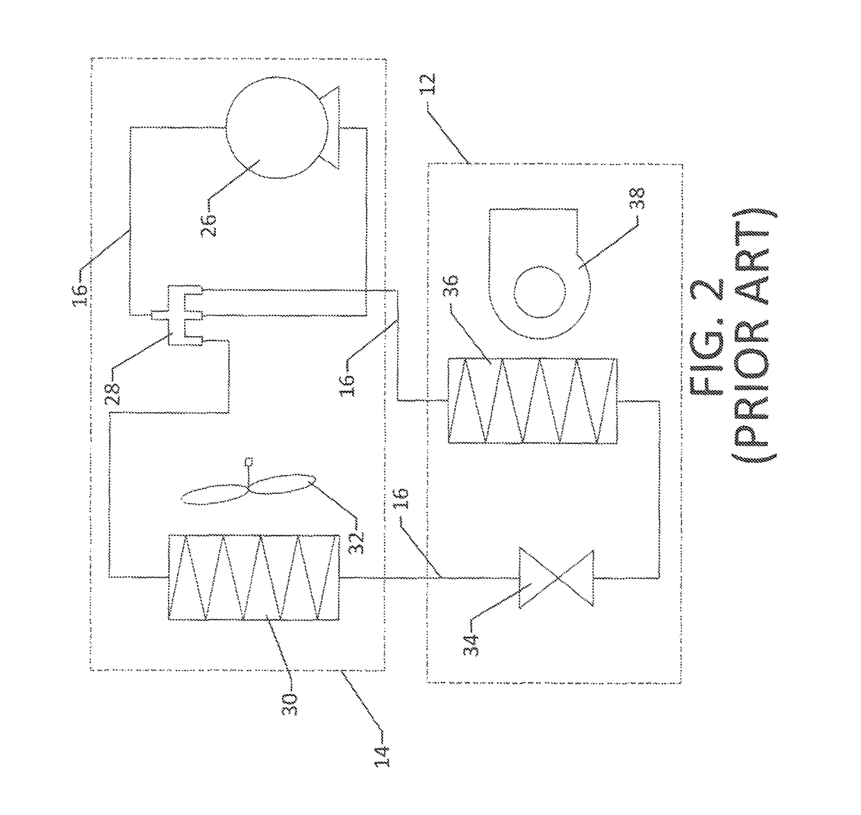
[0030]For the case of a heat pump HVAC system, the inventive device pulses the control line for the reversing valve. FIG. 2 shows a schematic of the refrigera...


PUM


Abstract

A device for pulsing the control lines of an HVAC system in order for a user to discover which outside unit is associated with a particular inside unit. Lead wires from the device connect to the control contacts on the thermostat of an HVAC unit. The device is an electrical or electromechanical circuit that can use the power contained within the thermostat or can be battery powered. Once the device is connected, it pulses the control line for the reversing valve, in the case of a heat pump system, or pulses the control line for the compressor, for a cooling-only system. This pulsing creates a loud clicking sound in either case that allows the repair technician to decipher the correct outside unit corresponding to the inside unit without use of a helper.

Description

CROSS-REFERENCES TO RELATED APPLICATIONS[0001]Not Applicable.STATEMENT REGARDING FEDERALLY SPONSORED RESEARCH OR DEVELOPMENT[0002]Not applicableMICROFICHE APPENDIX[0003]Not ApplicableBACKGROUND OF THE INVENTION[0004]1. Field of the Invention[0005]This invention relates to the field of heating, ventilation and air conditioning. More specifically, the invention comprises an electrical or electromechanical device that pulses the control line of an outdoor HVAC unit using the thermostat connections in order to indicate to a user which outdoor unit is associated with a particular indoor unit.[0006]2. Description of Related Art[0007]On most occasions heating, ventilation and air conditioning (HVAC) systems are set up with some components on the inside of a dwelling and some components on the outside. Such a system is often called a “split system.”FIG. 1 shows an example of a prior art split system. Inside unit 12 is located inside dwelling 10 while outside unit 14 is located outside the d...

Claims


Application Information

Patent Timeline
Patent Type & Authority Patents(United States)
IPC IPC(8): F24F1/20G08B3/02F24F11/02
CPCF24F1/20G08B3/02F24F11/02F24F11/30F24F11/62
Inventor JONES, RAY
Owner JONES RAY
Features
  • R&D
  • Intellectual Property
  • Life Sciences
  • Materials
  • Tech Scout
  • Unparalleled Data Quality
  • Higher Quality Content
  • 60% Fewer Hallucinations
Learn More