
Systems and methods for leadless pacemaker electronics assemblies

a technology of electronic assemblies and leadless pacemakers, applied in the field of electronic assemblies for leadless pacemakers, can solve the problems of prolonging patient recovery, body can be cut inadvertently, and skin can be bulged that patients can find unsightly or unpleasant,

Active Publication Date: 2018-01-02
PACESETTER INC
View PDF13 Cites 43 Cited by
  • Summary
  • Abstract
  • Description
  • Claims
  • Application Information

AI Technical Summary

Benefits of technology

The leadless pacemaker system provides effective cardiac pacing without external generators or leads, reducing surgical complexity, minimizing the risk of lead damage, and offering a more aesthetically pleasing solution with improved reliability and reduced recovery time for patients.

Problems solved by technology

Although more than one hundred thousand conventional cardiac pacing systems are implanted annually, several well-known difficulties exist.
For example, a pulse generator, when located subcutaneously, presents a bulge in the skin that patients can find unsightly or unpleasant.
Although sub-muscular or abdominal placement can address some concerns, such placement involves a more difficult surgical procedure for implantation and adjustment, which can prolong patient recovery.
Further, the lead body can be cut inadvertently during surgery by a tool, or cut after surgery by repeated stress on a ligature used to hold the lead body in position.
Moreover, repeated movement for hundreds of millions of cardiac cycles can cause lead conductor breakage or insulation damage anywhere along the lead body.

Method used


Image

  • Systems and methods for leadless pacemaker electronics assemblies
  • Systems and methods for leadless pacemaker electronics assemblies
  • Systems and methods for leadless pacemaker electronics assemblies

Examples


Embodiment Construction

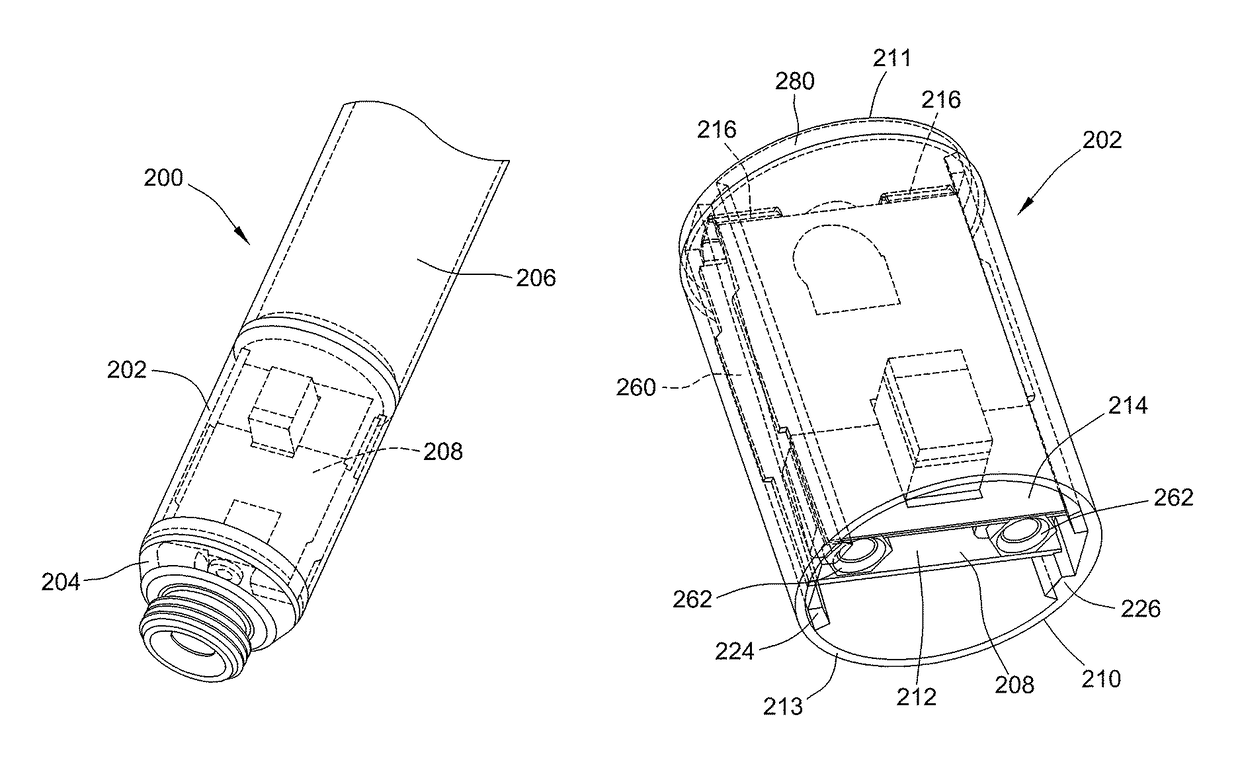
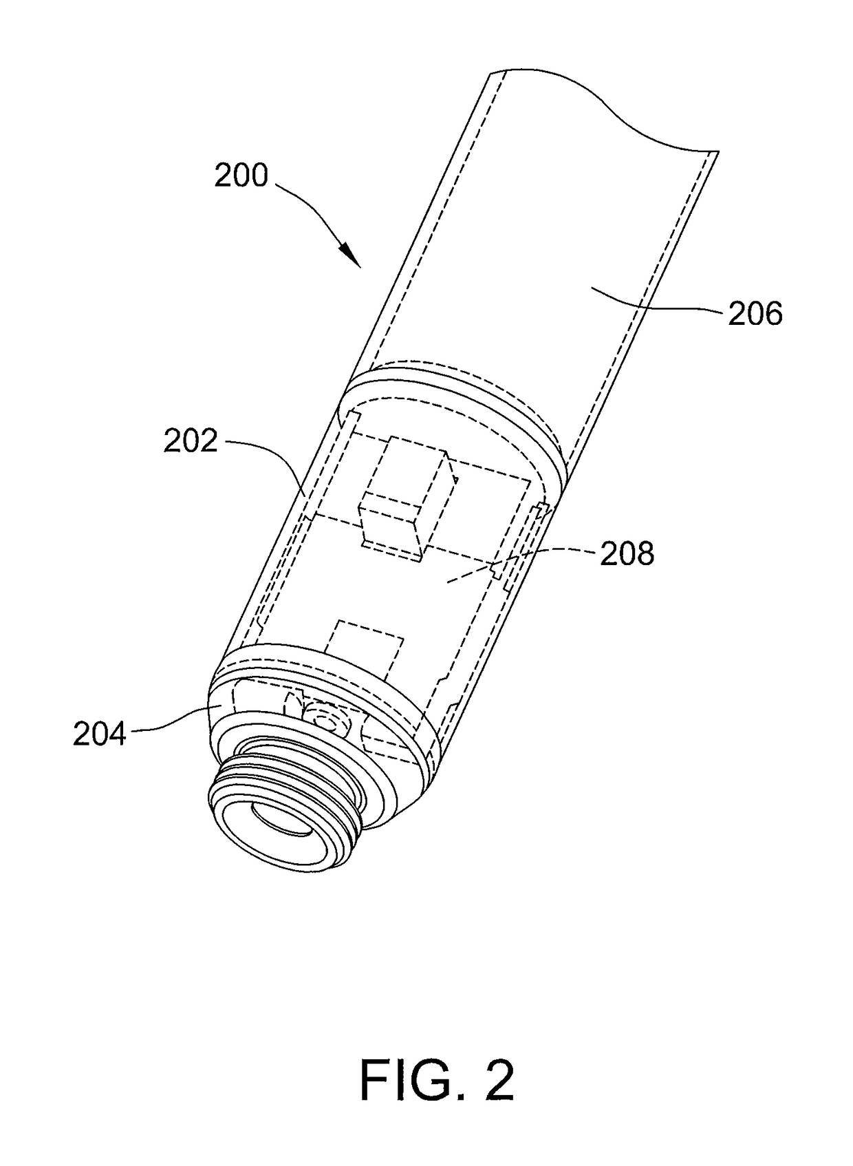
[0016]The systems and methods described herein facilitate reducing the cost and complexity of manufacturing leadless pacemakers. A leadless pacemaker includes a battery subassembly, a feedthrough subassembly, and an electronics subassembly coupled between the battery subassembly and the feedthrough subassembly. The electronics subassembly includes an electronics package, and a housing configured to provide a hermetic seal and comprising a first retaining feature and a second retaining feature configured to secure the electronics package within the housing.

[0017]In some embodiments of a cardiac pacing system, cardiac pacing is provided without a pulse generator located in the pectoral region or abdomen, without an electrode-lead separate from the pulse generator, without a communication coil or antenna, and without an additional requirement on battery power for transmitted communication.

[0018]An embodiment of a cardiac pacing system configured to attain these characteristics includes...


PUM


Abstract

The present disclosure provides leadless pacemaker systems and methods. A leadless pacemaker includes a battery subassembly, a feedthrough subassembly, and an electronics subassembly coupled between the battery subassembly and the feedthrough subassembly, the electronics subassembly including an electronics package, and a housing configured to provide a hermetic seal and comprising a first retaining feature and a second retaining feature configured to secure the electronics package within the housing.

Description

A. FIELD OF THE DISCLOSURE[0001]The present disclosure relates generally to methods and systems for cardiac pacing, and more particularly, to electronics assemblies for leadless pacemakers.B. BACKGROUND ART[0002]Cardiac pacing electrically stimulates the heart when the heart's natural pacemaker and / or conduction system fails to provide synchronized atrial and ventricular contractions at appropriate rates and intervals for a patient's needs. Such bradycardia pacing provides relief from symptoms and even life support for hundreds of thousands of patients. Cardiac pacing may also give electrical overdrive stimulation intended to suppress or convert tachyarrhythmias, again supplying relief from symptoms and preventing or terminating arrhythmias that could lead to sudden cardiac death.[0003]Cardiac pacing is typically performed by a pulse generator implanted subcutaneously or sub-muscularly in or near a patient's pectoral region. The generator usually connects to the proximal end of one ...

Claims


Application Information

Patent Timeline
Patent Type & Authority Patents(United States)
IPC IPC(8): A61N1/00A61N1/362A61N1/375A61N1/05
CPCA61N1/3756A61N1/362A61N1/0573
Inventor SAHABI, KAVOUSGARABED, AREES
Owner PACESETTER INC
Learn More