Method for implementing high-precision orientation and evaluating orientation precision of large-scale dynamic photogrammetry system

a dynamic photogrammetry and high-precision technology, applied in image analysis, image enhancement, instruments, etc., can solve the problems of not being suitable for large-scale measurement occasions having high requirements on precision and precision traceability, and unable to provide reliable objective spatial evaluation indicators, etc., to achieve convenient processing and measurement, improve accuracy, and simple calibration process

Active Publication Date: 2018-01-02
BEIJING INFORMATION SCI & TECH UNIV
View PDF5 Cites 20 Cited by
  • Summary
  • Abstract
  • Description
  • Claims
  • Application Information

AI Technical Summary

Benefits of technology

[0054]Based on the above, according to the method for high-precision positioning and orientation of a large-scale multi-camera photogrammetry system of the present invention, the photogrammetry system remains stable, positioning and orientation are completed at the measurement site, the calibration object is convenient to process and measure, and the calibration process is simple. Once the orientation process is completed, traceable evaluation of the length measurement error of the photogrammetry system can be provided. The present invention achieves the following technical effects:
[0055]1. In the present invention, the measurement space is divided into regions so that the distance between the left and right cameras is equal to the region length of the divided space, and the gauge attitude and the camera position are adjusted at the same time during the photographing process, making the length orientation field more reliable.

Problems solved by technology

Such self-calibration methods have the following defects: the focus of the adjustment process is the interior orientation parameter, and there is no direct optimization or evaluation on the orientation relationship between cameras; coordinate precision of target points on the calibration plate that are used as control points leads to a system error; differences between the target points on the calibration plate and the measurement points in material and imaging quality lead to a system error; in addition to the image plane error or spatial coordinate error estimation, there is no reliable objective spatial evaluation indicators.
Therefore, such method are not suitable for large-scale measurement occasions having high requirements on precision and precision traceable.

Method used


Image

  • Method for implementing high-precision orientation and evaluating orientation precision of large-scale dynamic photogrammetry system
  • Method for implementing high-precision orientation and evaluating orientation precision of large-scale dynamic photogrammetry system
  • Method for implementing high-precision orientation and evaluating orientation precision of large-scale dynamic photogrammetry system

Examples


Embodiment Construction

[0064]The objectives and functions of the present invention and methods for achieving such objectives and functions will be illustrated through exemplary embodiments. However, the present invention is not limited to the exemplary embodiments disclosed below, but may be implemented in different forms. The essence of this specification is merely for the purpose of helping those skilled in the art to comprehensively understand the specific details of the present invention.

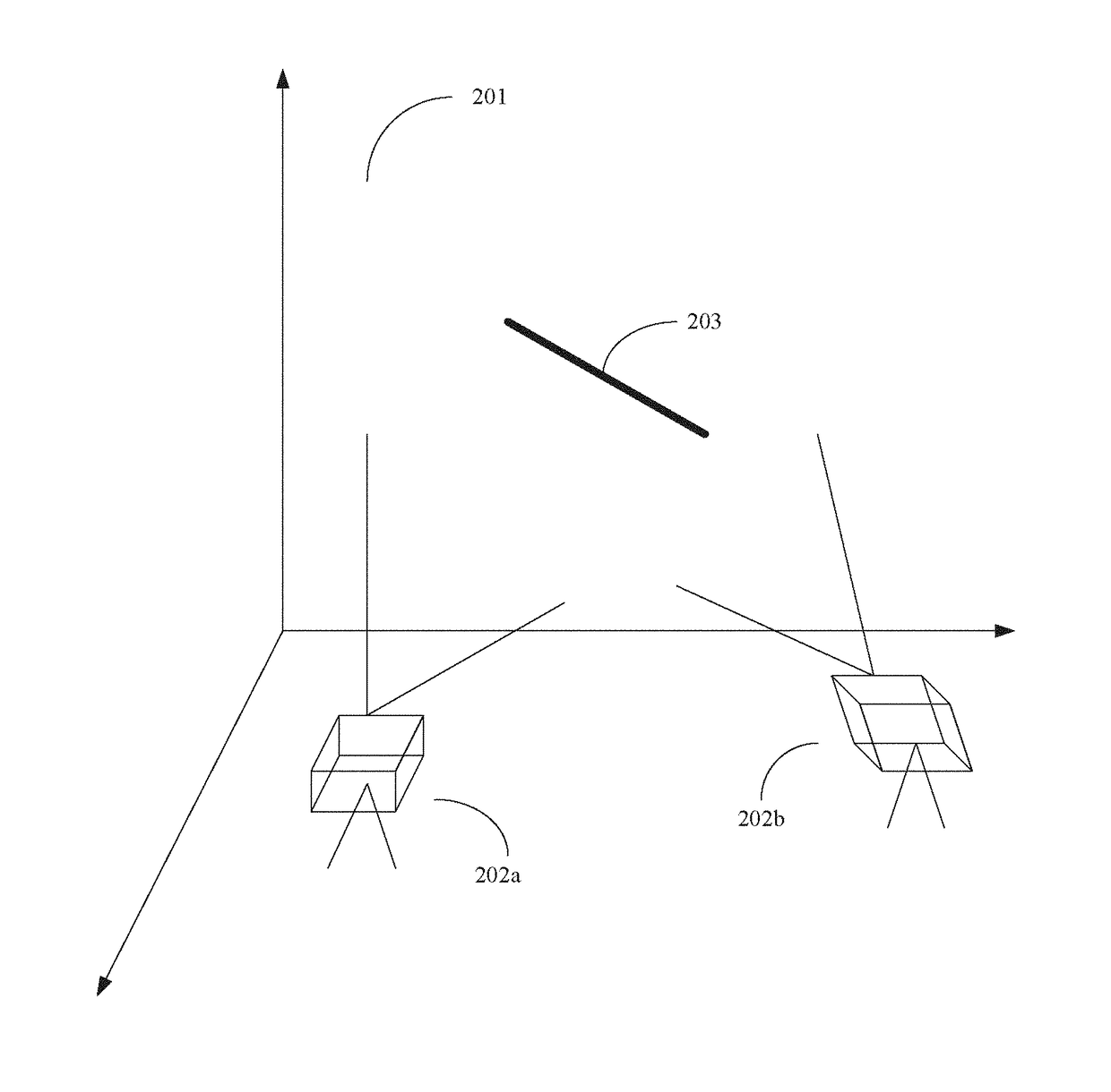
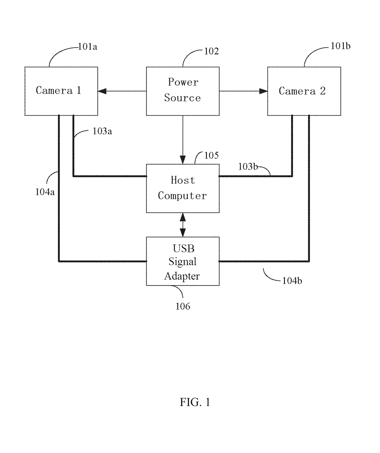
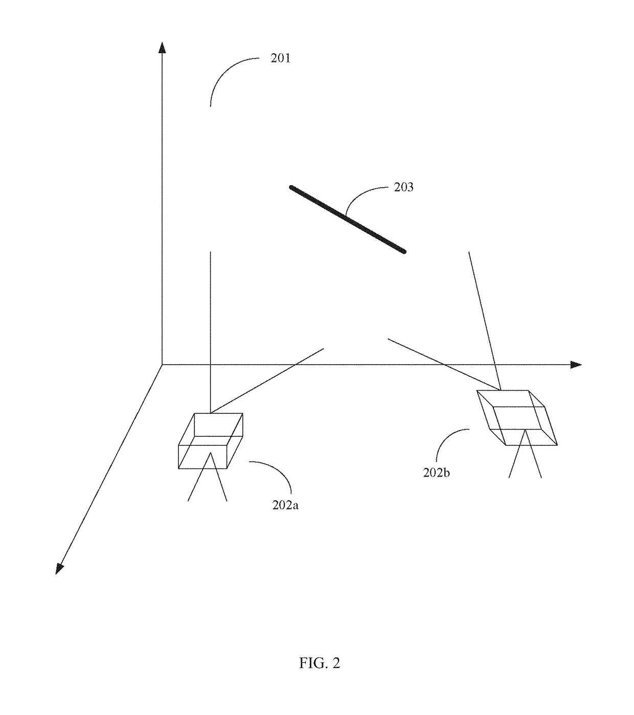
[0065]The present invention provides a large-scale dynamic photogrammetry system. The system includes a camera 101, a power source 102, a network cable 103, a signal line 104 and a host computer 105. The power source 102 supplies power to the camera 1, the camera 2 and the host computer 105. A network cable 103a is connected between the camera 1 and the host computer 105, and a network cable 103b is connected between the camera 2 and the host computer 105, for providing communication between the cameras and the host c...


PUM


Abstract

The present invention provides a method for implementing high-precision orientation and evaluating orientation precision of a large-scale dynamic photogrammetry system, including steps: a) selecting a scale bar, arranging code points at two ends of the scale bar, and performing length measurement on the scale bar; b) evenly dividing a measurement space into multiple regions, sequentially placing the scale bar in each region, and photographing the scale bar by using left and right cameras; d) limiting self-calibration bundle adjustment by using multiple length constraints, adjustment parameters including principal point, principal distance, radial distortion, eccentric distortion, in-plane distortion, exterior orientation parameter and spatial point coordinate; and e) performing traceable evaluation of orientation precision of the photogrammetry system. The present invention can effectively reduce the relative error in length measurement.

Description

FIELD OF THE INVENTION[0001]The present invention relates to a method for implementing high-precision orientation and evaluating orientation precision, and more particularly to a method for implementing high-precision orientation and evaluating orientation precision of a large-scale dynamic photogrammetry system.BACKGROUND OF THE INVENTION[0002]A dynamic photogrammetry system includes two or more cameras that can capture images at a high speed. The cameras synchronously capture images of a target point to be measured. By calibrating projection imaging models of the cameras, spatial light may be restored from image plane points, and spatial coordinates of the point to be measured may be calculated from an intersection of the spatial light. Imaging models of cameras include interior and exterior orientation parameter types. Interior orientation parameters include principal point, principal distance and various distortion parameters of different orders. Exterior orientation parameters ...

Claims


Application Information

Patent Timeline
Patent Type & Authority Patents(United States)
IPC IPC(8): G06K9/36G01C11/14G01C11/10G06T7/73G06T7/80G06T7/77G06T3/40G06F17/18
CPCG01C11/10G01C11/14G06T7/85G06T7/77G06T3/40G06T7/75G06F17/18G06T2200/21G06T2207/30244
Inventor DONG, MINGLISUN, PENGLI, WEIWANG, JUNYAN, BIXILV, NAIGUANG
Owner BEIJING INFORMATION SCI & TECH UNIV
Why Eureka
Try Eureka