Self-biasing output booster amplifier and use thereof

a technology of output booster amplifier and self-biasing, which is applied in the direction of low frequency amplifier, gated amplifier, amplifier, etc., can solve the problems of reducing the efficiency of supply current, and achieve the effect of facilitating implementation and integration of a stabile high pass filter, facilitating use, and less feed

Active Publication Date: 2018-01-09
SONION NEDERLAND
View PDF98 Cites 0 Cited by
  • Summary
  • Abstract
  • Description
  • Claims
  • Application Information

AI Technical Summary

Benefits of technology

[0017]The self-biasing concept of the output booster amplifier of the present invention facilitates that the output booster amplifier may advantageously be used in two wire applications. In the present context the term “self-biasing” implies that the output booster amplifier will balance its internal bias currents through its components itself via a negative feedback path.
[0019]The self-biasing output booster amplifier according to the present invention is advantageous over prior art systems in various ways. Firstly, the self-biasing output booster amplifier of the present invention may apply a fixed external bias current source. This facilitates use in particular in relation to two wire amplifier configurations. The circuit topology of the self-biasing output booster amplifier facilitates implementation and integration of a stabile high pass filter. Due to the circuit topology a low frequency signal at the input stage output will have less feed through to the output node. The self-biasing output booster amplifier currents flow through the current mirrors and the output stage and contribute directly to the output signal level. No other fixed current source is required inside the self-biasing output booster amplifier circuit. This may reduce the supply current efficiency which is ideal for lower power applications.
[0020]The topology of the self-biasing output booster amplifier of the present invention is advantageous in that its frequency response is essentially unaffected by the level of an input signal applied to an input amplifier stage of the self-biasing output booster amplifier.

Problems solved by technology

This may reduce the supply current efficiency which is ideal for lower power applications.

Method used


Image

  • Self-biasing output booster amplifier and use thereof
  • Self-biasing output booster amplifier and use thereof
  • Self-biasing output booster amplifier and use thereof

Examples


Embodiment Construction

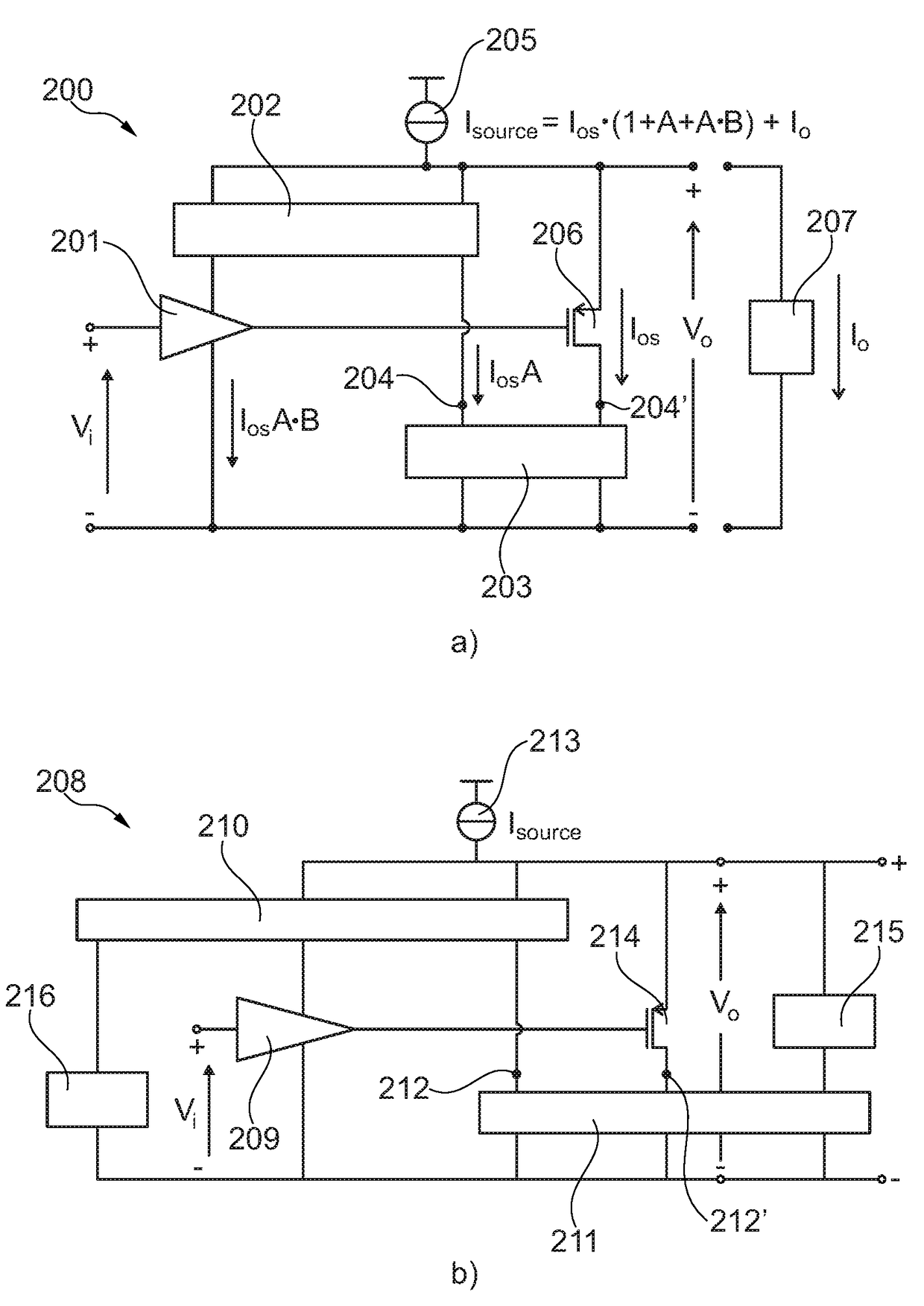
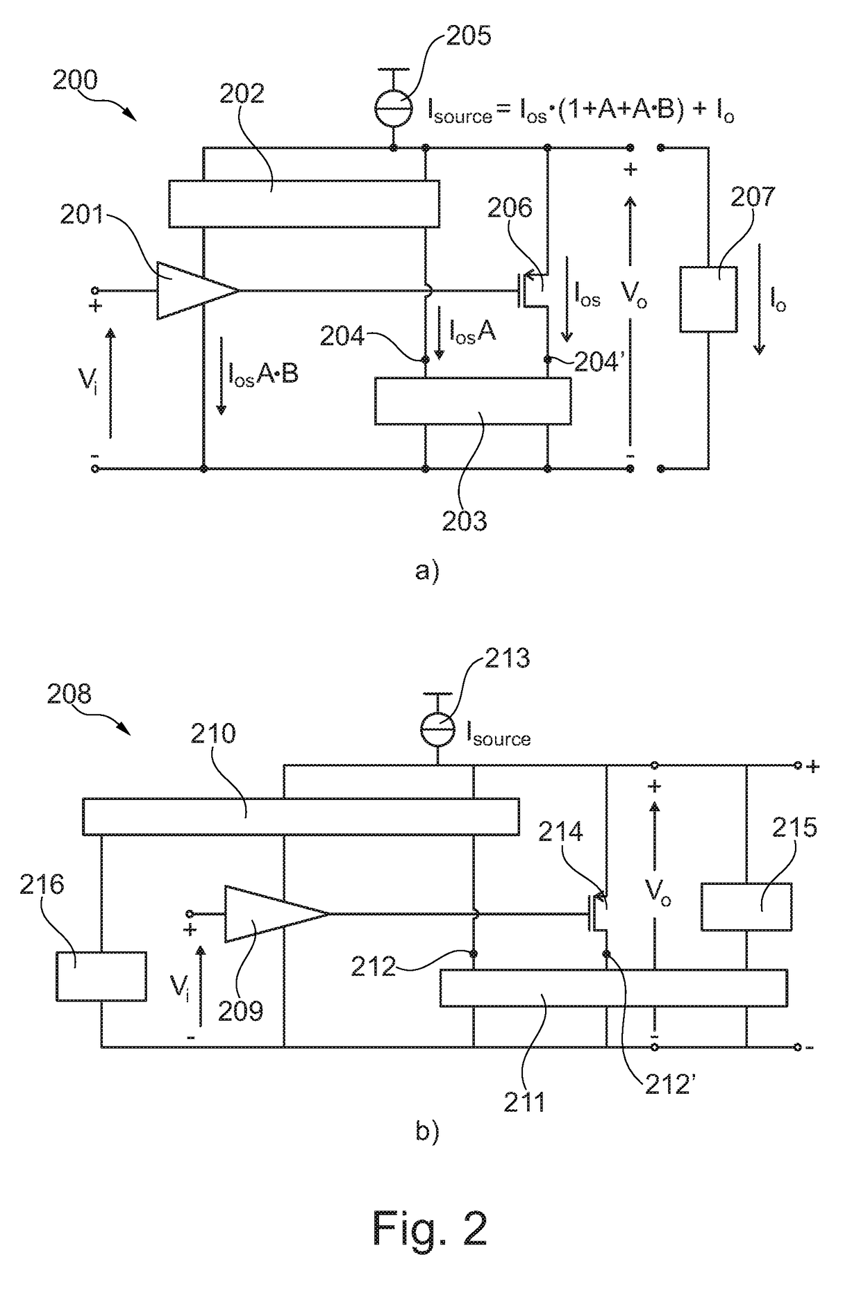
[0046]In its broadest aspect the present invention relates to an amplifier circuit having a frequency response which is essentially unaffected by a signal level arriving at an input amplifier stage of the amplifier circuit. The amplifier circuit may have a filter stage incorporated therein. The amplifier circuit is implemented in such a way that the filter stage is essentially unaffected by a signal level being provided to an input amplifier stage of the amplifier circuit. The amplifier circuit of the present invention is of the type two wire self-biasing output booster amplifier.

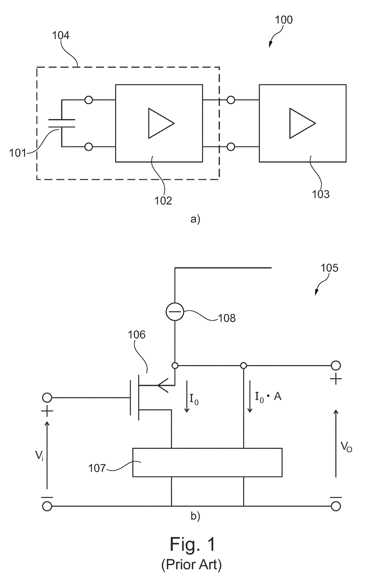
[0047]Referring now to FIG. 1a a prior art arrangement 100 comprising a microphone 104 and a DSP 103 is depicted. Such arrangements are typically applied in hearing devices. As seen in FIG. 1a the microphone 104 comprises a microphone cartridge 101 and a two wire amplifier 102 being connected thereto. The microphone cartridge 101 may be a micro electro-mechanical system (MEMS) cartridge or an electret cartr...


PUM


Abstract

A self-biasing output booster amplifier having an input amplifier stage, an output amplifier stage being operatively connected to an output of the input amplifier stage, and first and second current copying circuits. The second current copying circuit is biased from an output of the self-biasing output booster amplifier. The first and second current copying circuits are configured to copy at least a portion of the current through the output amplifier stage. The sum of the output of the second current copying circuit and the output of the output amplifier stage provides the output current of the self-biasing output booster amplifier, Finally, the input amplifier stage is biased from the output of the second current copying.

Description

CROSS-REFERENCE TO RELATED APPLICATION[0001]This application claims the benefit of European Patent Application Serial No. 16152518.3, filed Jan. 25, 2016, which is incorporated herein by reference in its entirety.FIELD OF THE INVENTION[0002]The present invention relates to a self-biasing output booster amplifier and the use thereof in connection with for example a sensor module.BACKGROUND OF THE INVENTION[0003]Various electronic filter arrangements for processing signals in hearing devices have been suggested over the years. Examples of such arrangements can for example be found in US 2014 / 0097906 A1, U.S. Pat. No. 6,888,408 B1, GB 2 266 021 A as well as the paper titled “An enhanced slew rate source follower”, IEEE Journal of solid-state circuits (Vol 30, No 2, 1 Feb. 1995, pages 144-146) by Kenney J G et al.[0004]Referring now to US 2014 / 0097906 A1 an amplifier having a high-pass filter is suggested. However, this high-pass filter has a major drawback in that its cut-off frequency...

Claims


Application Information

Patent Timeline
Patent Type & Authority Patents(United States)
IPC IPC(8): H04R3/00H03F3/185H04R19/04
CPCH04R3/005H03F3/185H04R19/04H03F2200/171H03F2200/03H03F1/303H03F1/3205H03F3/187H03F3/211H03F3/505H03F3/72H03F2200/168H03F2200/18H03F2200/219H03F2200/297H03F2200/411H03F2200/474H03F2200/54H03F2200/69H03F2203/21161H03F2203/5012H03F2203/5021H03F2203/5027
Inventor VAN NIEUWKERK, MICHIELGAO, YANG
Owner SONION NEDERLAND
Why Eureka
Try Eureka