Induction cooking device for temperature-controlled cooking

a technology of induction cooking and cooking support, which is applied in the direction of temperature measurement in household appliances, instruments, heat measurement, etc., can solve the problems of affecting the heating effect of the underside affecting the heating effect of the cooking support, and unable to measure the temperature of the bottom of the cooking pan in real tim

Active Publication Date: 2018-01-09
GARLAND COMML IND INC
View PDF15 Cites 69 Cited by
  • Summary
  • Abstract
  • Description
  • Claims
  • Application Information

AI Technical Summary

Problems solved by technology

A measuring of the temperature of the bottom of the cooking pan in real time is thus almost impossible.
This problem is also present in induction cooking devices, since here, in contrast to thermal cooking devices, the cooking pan is heated directly.
The product to be cooked is heated in turn indirectly by the heated cooking pan, but with a certain time delay.
If, in addition, the cooking support has thermally insulating properties, then the time delay by means of which the underside of the cooking support is heated is still greater.
A control of temperature exclusively by measuring the temperature of the cooking support by means of the named temperature sensors is thus not very suitable and is at most suitable for cooking or keeping warm within a constant temperature range without large temperature shifts.
The alternating magnetic field in turn, among other things, induces eddy currents in the induction cooking pan, in particular in its bottom, which contributes to the heating of the cooking pan, in addition to hysteresis and magnetization losses.
This method, however, has the disadvantage that each induction cooking pan must be registered in the induction cooking device prior to use.
This procedure is relatively cumbersome and, in particular, leads to unnecessary delays, erroneous identification of the cooking pan, and consequently to poorer cooking results during the hectic operation of a professional kitchen.
A large disadvantage of the method, however, also lies in the fact that the determination of the temperature calibration values upon first-time use of the pan must be made with the induction cooking device independently from the cooking process, e.g., prior to cooking.
This would very much hinder the cooking process, in that the determination of the temperature calibration values cannot be carried out during the cooking process.
An additional calibration of the induction cooking pan in a separately conducted calibration process also means, however, an additional expense.

Method used


Image

  • Induction cooking device for temperature-controlled cooking
  • Induction cooking device for temperature-controlled cooking
  • Induction cooking device for temperature-controlled cooking

Examples


Embodiment Construction

[0090]In the following, the subject of the invention is explained in more detail based on the figures. Here, schematically:

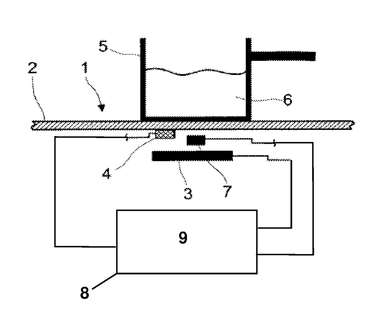
[0091]FIG. 1 shows a representation of the cooking zone of an induction cooking device;

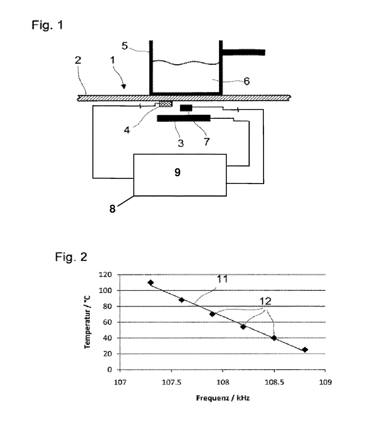
[0092]FIG. 2 shows the graphic representation of the linear characteristic between the temperature of the article and the resonant frequency of an induction measuring resonant circuit.

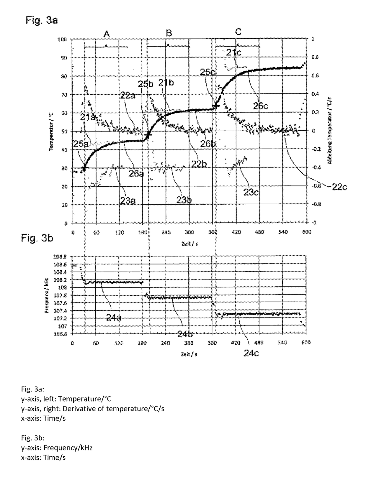
[0093]FIG. 3a shows the graphic representation of the temperature step response of a PT1-element as a function of the resonant frequency;

[0094]FIG. 3b shows a representation of the resonant frequency for the step response according to FIG. 3a;

[0095]FIG. 4a shows the graphic representation of the temperature step response of a PT2-element as a function of the resonant frequency;

[0096]FIG. 4b shows a representation of the resonant frequency for the step response according to FIG. 4a.

[0097]A schematic arrangement for conducting the method according to the invention is shown in FIG. 1. An induction...


PUM

PropertyMeasurementUnit
measurement timeaaaaaaaaaa
temperatureaaaaaaaaaa

Abstract

The invention relates to a method for determining and regulating the temperature of an article with inductive properties which is heated inductively by means of an induction device, wherein the induction device contains an induction coil, means for producing an induction resonant circuit and a support element arranged above the induction coil and having a first side, which acts as support face for the article, and a second side, which is directed towards the inductive coil. At least one temperature sensor is fitted to the second side. The resonant frequency of the induction resonant circuit is measured via detection means and the temperature of the article is calculated from the measured resonant frequency, wherein the resonant frequency is related to the temperature of the article by virtue of a mathematical function, and the function is determined by determining at least two absolute temperature calibration values of the article at respectively different resonant frequencies. The temperature calibration values are calculated from temperature measured values of the sensor.

Description

[0001]The invention belongs to the field of electrical devices for heating a utensil or pan, in particular, for restaurants. The invention generally relates to a method for determining the temperature of an article having inductive properties, which is heated by means of an electrical mechanism, a support element that forms a bearing surface for the article being disposed above the electrical mechanism.[0002]Further, the invention relates to an electrical device for heating an article having inductive properties. The device contains an electrical mechanism for heating the article, [and]* a support element forming a bearing surface for the article, this support element being disposed above the electrical mechanism. * Text in brackets is added for clarity.—Translator's note.PRIOR ART[0003]In professional food preparation, the temperature and the temperature control considerably influence the quality of prepared foods. For example, meat, fish and sauces must be prepared in a very narro...

Claims


Application Information

Patent Timeline
Patent Type & Authority Patents(United States)
IPC IPC(8): H05B6/12G01K15/00G01K7/38G05D23/26G01K17/00H05B1/02H05B6/06H05B6/08
CPCH05B6/06G01K7/38G01K15/005G01K17/00H05B1/0266H05B6/062G05D23/26H05B2213/07G01K2207/06
Inventor THOMANN, ALBERTVOGEL, ANDREASFUCHS, CHIRSTIAN
Owner GARLAND COMML IND INC
Why Eureka
Try Eureka