Method for balancing the voltage of battery cells

a battery cell and voltage balancing technology, applied in the direction of battery/fuel cell control arrangement, electric devices, propulsion by batteries/cells, etc., can solve the problem of limiting the capacity and lifetime of the battery pack as a whole, shortening the overall balancing time of the battery cell, and affecting the discharge rate of the electrical storage system. , the effect of high discharge rate of the electrical storage system

Active Publication Date: 2018-01-16
VOLVO LASTVAGNAR AB
View PDF21 Cites 3 Cited by
  • Summary
  • Abstract
  • Description
  • Claims
  • Application Information

AI Technical Summary

Benefits of technology

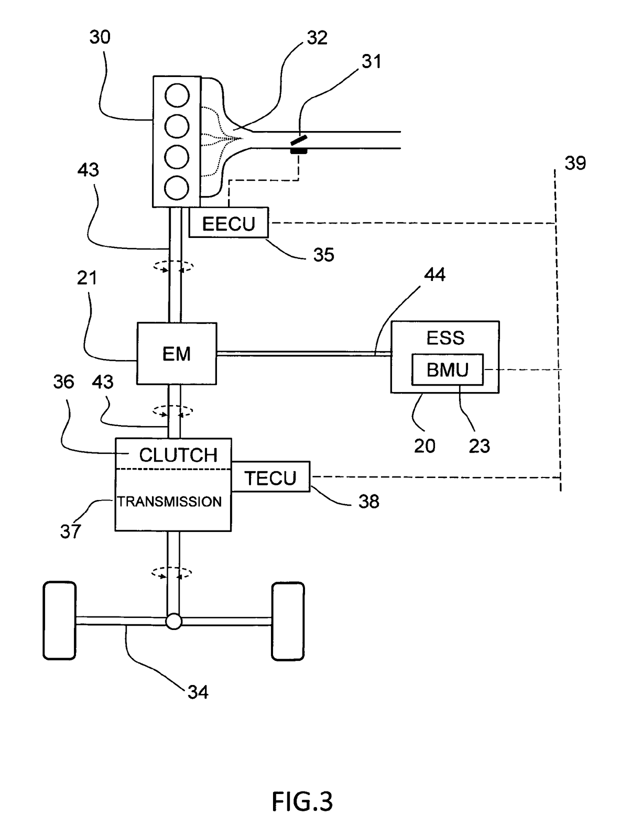
[0009]By discharging the electrical storage system, prior to balancing, by operating at least one large electrical machine of the vehicle, the discharge power can be kept high while avoiding the heat release that would arise within the energy storage unit if discharge of the electrical storage system would be performed by means of internal balancing resistors. This leads to considerably shorter discharge times, such that the overall battery cell balancing time can be reduced.
[0018]The method may further comprise discharging the electrical storage system by simultaneously operating at least one additional electrical consumer of the vehicle, wherein the additional electrical consumer is any of an electrical heating radiator or an electrical power resistor system configured as a current sink. The additional electrical consumer contributes to increasing the discharge rate of the electrical storage system.

Problems solved by technology

However, no two cells are identical—there are always slight differences in for example capacity, state of charge, and self-discharge rate.
The capacity and lifetime of the weakest cell limit the capacity and lifetime of the battery pack as a whole.
In order to limit the temperature increase, the discharge power has to be low which in turn leads to an overall long battery cell balancing time.
A high discharge rate generally results in high beat generation from the electrical storage system.
As a consequence, an ESS having a relatively large unbalance between the individual cells of the ESS may according to this ESS SOC determination method become over discharged and thus permanently damaged even if the estimated ESS SOC is within an acceptable SOC interval.
If one weak cell prematurely runs out of charge cycles due to overcharging or excessive discharging, the entire pack of series-connected cells will have to be repaired or replaced.

Method used


Image

  • Method for balancing the voltage of battery cells
  • Method for balancing the voltage of battery cells
  • Method for balancing the voltage of battery cells

Examples


Embodiment Construction

[0029]Various aspects of the disclosure will hereinafter be described in conjunction with the appended drawings to illustrate and not to limit the disclosure. Like designations denote like elements, and variations of the described aspects are not restricted to the specifically shown embodiments, but are applicable on other variations of the disclosure.

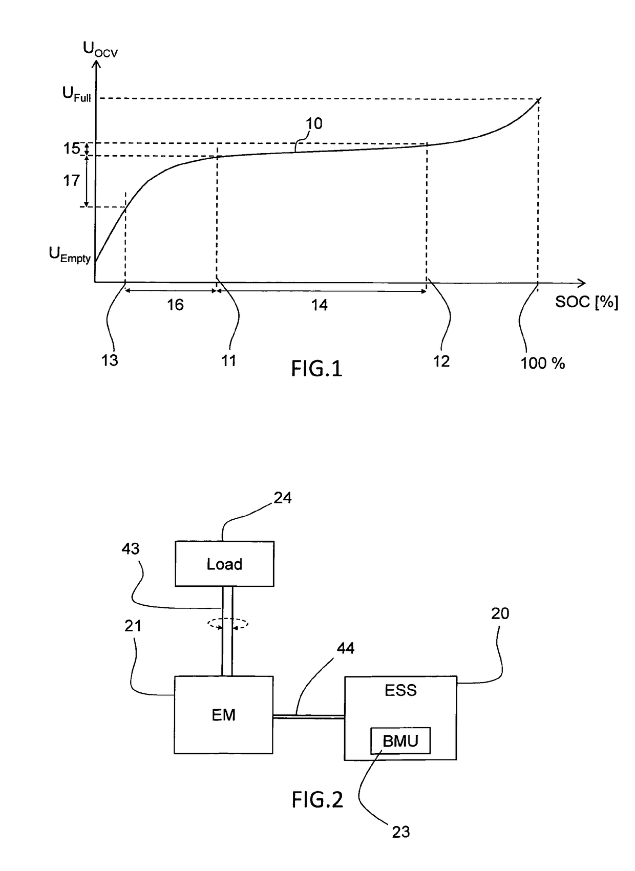
[0030]FIG. 1 shows a graph of the output open circuit voltage OCV as a function of the chemical state of charge SOC of a typical electrochemical cell, which graph is also commonly referred to as “voltage discharge curve”. The electrochemical cell may preferably be a lithium cell. The electrical storage system may comprise at least 100 series-connected electrochemical cells and preferably at least 150 series-connected cells, for example lithium cells. The electrical storage system may also be referred to as a battery pack and the output voltage of the electrical storage system equals the accumulated output voltage of each cell of a comm...


PUM


Abstract

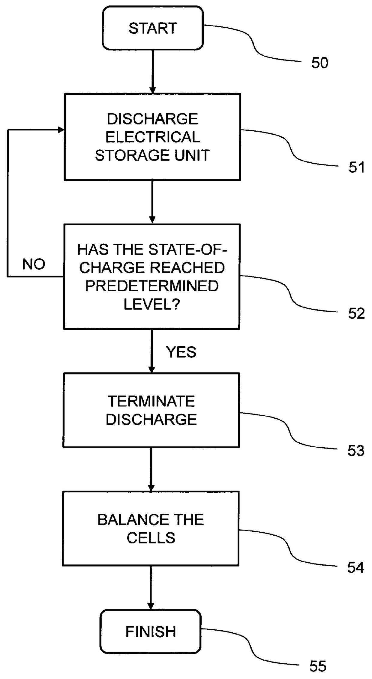
A method is provided for balancing the voltage of multiple series-connected electrochemical cells of an electrical storage system of a hybrid electric vehicle. The method includes discharging the electrical storage system by operating at least one large electrical machine of the vehicle at vehicle standstill until the state of charge of the electrical storage system or the cell having the lowest state of charge has reached a predetermined level, and subsequently balancing the voltage of the cells.

Description

BACKGROUND AND SUMMARY[0001]This disclosure relates to a method for balancing the voltage of multiple series-connected electrochemical cells of an electrical storage system of a hybrid electric vehicle. The method comprises the step of discharging the electrical storage system before cell balancing. The disclosure also relates to a hybrid electric vehicle comprising an electrical storage system, wherein a battery management unit of the electrical storage system is configured to discharge the electrical storage system before cell balancing. The disclosure is particularly advantageous in the field of electrical storage systems for heavy hybrid vehicles, such as trucks, buses, construction vehicles, or the like.[0002]The electrical storage systems in electric and hybrid electric vehicles commonly comprise battery packs of multiple series-connected electrochemical cells, typically hundreds of lithium cells. However, no two cells are identical—there are always slight differences in for e...

Claims


Application Information

Patent Timeline
Patent Type & Authority Patents(United States)
IPC IPC(8): H02J7/00B60L3/12B60L3/00B60L15/20B60L11/18B60L7/20B60L11/14B60L11/16B60L1/00B60L50/16B60L50/30
CPCB60L11/1866B60L1/006B60L3/0046B60L3/12B60L7/20B60L11/14B60L11/16B60L11/1803B60L11/1861B60L11/1862B60L15/20B60L15/2009H02J7/0014H02J7/0016B60L1/003Y02T10/7275B60L2200/18B60L2200/36B60L2240/34B60L2240/423B60L2240/545B60L2240/547B60L2240/549B60L2240/80B60L2260/44Y02T10/645Y02T10/70Y02T10/7005Y02T10/7044Y02T10/7055Y02T10/7061Y02T10/7077Y02T10/72B60L50/16B60L50/30B60L50/51B60L58/13B60L58/22H02J2310/48Y02T10/64Y02T10/7072
Inventor SMIDEBRANT, TOBIASLENNEVI, JERKER
Owner VOLVO LASTVAGNAR AB
Why Eureka
Try Eureka